Light emitting diode and preparation method thereof

A technology of light-emitting diodes and light-emitting layers, applied in electrical components, circuits, semiconductor devices, etc., can solve the problems of increasing the adhesion between the light-emitting layer and the chip, and the easy precipitation of phosphors, so as to improve the uniformity of the glue and reduce the production cost. , The effect of improving the consistency of light output

Inactive Publication Date: 2013-03-13
UNIV OF ELECTRONICS SCI & TECH OF CHINA
View PDF0 Cites 0 Cited by
  • Summary
  • Abstract
  • Description
  • Claims
  • Application Information

AI Technical Summary

Problems solved by technology

[0004] The technical problem to be solved by the present invention is how to provide a light-emitting diode and its preparation method. This solution solves the problems of colloid solidification and phosphor easy to precipitate in the colloid in the process of coating phosphor powder, and improves the glue output during the dispensing process. The uniformity of the light-emitting layer increases the consistency of the light-emitting layer in the light-emitting diode, increases the bonding degree between the light-emitting layer and the chip, and reduces the time required for curing the light-emitting layer; the solution is simple and effective, and can greatly reduce the production cost of the device and process difficulty, greatly improving the yield of related devices

Method used


Image

  • Light emitting diode and preparation method thereof
  • Light emitting diode and preparation method thereof
  • Light emitting diode and preparation method thereof

Examples


Embodiment 1

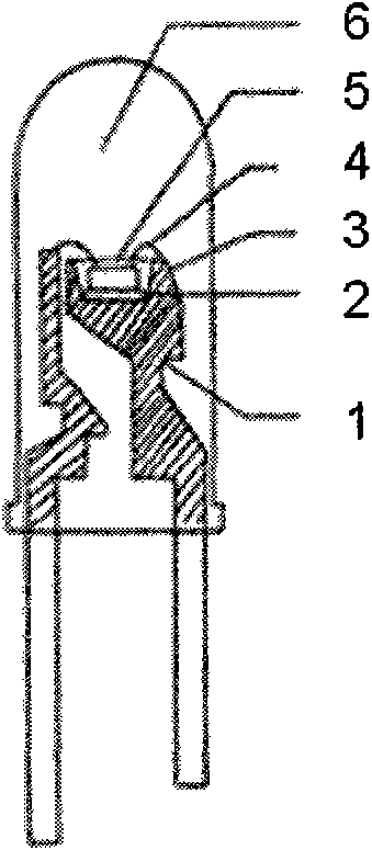
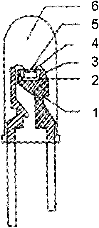
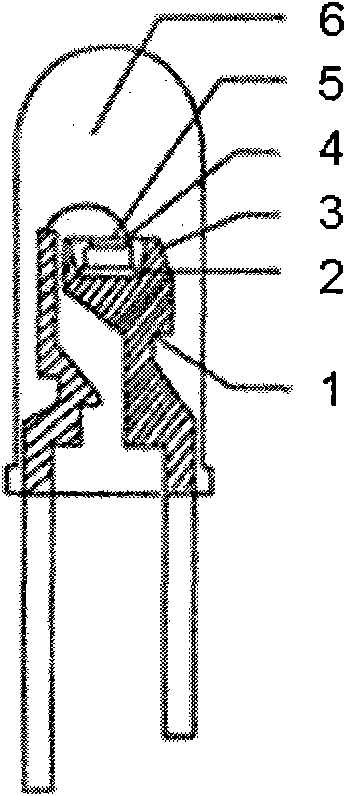
[0090] Such as figure 2 In the device structure shown, the LED chip 3 is a blue LED chip, the luminescent layer 5 is a mixed system of fluorescent powder excited by blue light to produce yellow light and an adhesive that needs to be cured by ultraviolet light, and the bracket 1 is a copper bracket with a silver-plated surface.

[0091] The preparation method is as follows:

[0092] ①Choose a suitable die-bonding glue to glue the blue LED chip on the bracket;

[0093] ② Lead out the electrodes on the LED chip;

[0094] ③ drop-coat the luminescent layer material on the LED chip, the luminescent layer is a mixed system of yellow fluorescent powder and an adhesive that needs to be cured by ultraviolet light, and the adhesive raw material includes the following components in mass percentage:

[0095] Unsaturated polyester resin or acrylic resin 95%

[0096] Styrene and its derivatives 1%

[0097] Photoinitiator 2%

[0098] Photosensitizers and additives 2%

[0099] ④ UV-curi...

Embodiment 2

[0106] Such as figure 2 As shown in the device structure, the LED chip 3 is a blue LED chip, the light-emitting layer 5 is a mixed system of fluorescent powder excited by blue light to generate green light and an adhesive that needs to be cured by ultraviolet light, and the bracket 1 is a copper bracket with silver-plated surface.

[0107] The preparation method is as follows:

[0108] ①Choose a suitable die-bonding glue to glue the blue LED chip on the bracket;

[0109] ② Lead out the electrodes on the LED chip;

[0110] ③ Spraying the luminescent layer material on the LED chip, the luminescent layer is a mixed system of green fluorescent powder and an adhesive that needs to be cured by ultraviolet light, and the adhesive raw material includes the following components in mass percentage:

[0111] Unsaturated polyester resin or acrylic resin 95%

[0112] Styrene and its derivatives 0.5%

[0113] Photoinitiator 4%

[0114] Photosensitizers and additives 0.5%

[0115] ④ U...

Embodiment 3

[0119] Such as figure 2 As shown in the device structure, the LED chip 3 is a blue LED chip, the light-emitting layer 5 is a mixed system of fluorescent powder excited by blue light to generate red light and an adhesive that needs to be cured by ultraviolet light, and the bracket 1 is a copper bracket with a silver-plated surface.

[0120] The preparation method is as follows:

[0121] ①Choose a suitable die-bonding glue to glue the blue LED chip on the bracket;

[0122] ② Lead out the electrodes on the LED chip;

[0123] ③ Dip-coating the luminescent layer material on the LED chip, the luminescent layer is a mixed system of red fluorescent powder and an adhesive that needs to be cured by ultraviolet light, and the raw material of the adhesive includes the following components in mass percentage:

[0124] Unsaturated polyester resin or acrylic resin 95%

[0125] Styrene and its derivatives 0.6%

[0126] Photoinitiator 1.4%

[0127] Photosensitizers and additives 3%

[0...


PUM


Abstract

The invention discloses a light emitting diode. The light emitting diode at least comprises a bracket, an LED chip and a luminescent layer on the LED chip. The light emitting diode is characterized in that: the luminescent layer is a mixed system of one or more kinds of fluorescent powder capable of emitting light of various colors and an adhesive needing curing by ultraviolet light; the adhesive raw materials comprise the following components: unsaturated polyester resin or acrylic acid resin, styrene and derivatives thereof, photo initiator, photosensitizer and additive. The luminescent layer solves the problems of colloid solidification and fluorescent powder precipitation in the process of coating the fluorescent powder, improves uniformity of the fluorescent powder on the chip, improves adhesive property of the luminescent layer and the chip and shortens the curing time of the luminescent layer at the same time.

Description

technical field [0001] The invention relates to the technical field of optoelectronic devices, in particular to a light emitting diode and a preparation method thereof. Background technique [0002] Light Emitting Diode (LED for short) is a light-emitting device that emits ultraviolet, visible or infrared light when a forward voltage is applied across a semiconductor p-n junction. It is a new generation of solid-state light source. Because of its small size, long life, low driving voltage, fast response, shock resistance, heat resistance and other characteristics, since the first light-emitting diode came out in 1964, people have not stopped the pace of research and development. With the development of light-emitting materials The development and improvement of semiconductor manufacturing process, as well as the introduction of distributed Bragg reflection structure, optical microcavity and quantum well structure in the chip growth process, have continuously improved the eff...

Claims


Application Information

Patent Timeline
Patent Type & Authority Patents(China)
IPC IPC(8): H01L33/50H01L33/56
Inventor 于军胜胡玉才陈苏杰蒋亚东
Owner UNIV OF ELECTRONICS SCI & TECH OF CHINA
Why Eureka
Try Eureka