Controlled silicon zero-voltage turn-on module of temperature control electric blanket and implementation method thereof

A technology for opening modules and electric blankets, applied in electric heating devices, electronic switches, electrical components, etc., can solve problems affecting product service life, switching noise, circuit electromagnetic interference, etc., to extend service life, reduce change rate, and reduce interference. Effect

Inactive Publication Date: 2012-06-27
BEIJING MXTRONICS CORP +1
View PDF0 Cites 0 Cited by
  • Summary
  • Abstract
  • Description
  • Claims
  • Application Information

AI Technical Summary

Problems solved by technology

[0005] In the previous electric blanket controller, because the power switching device - the thyristor gate trigger signal did not have any time point control, its power output was carried out at any point (often the peak value) of the AC half wave, and the thyristor was at Under the condition of high voltage or current between the anode and the cathode, it is turned on under the control of the gate. Since the voltage and current are not zero during the turn-on process, there is overlap, which leads to switching loss and the temperature of the thyristor rises. , which affects the life of the device, and the voltage and current change rapidly, and the waveform has obvious overshoot, which leads to the generation of switching noise. The typical turn-on process is as follows figure 2 As shown, such a SCR turn-on process brings serious electromagnetic interference problems to the circuit, and the electromagnetic radiation is large, which affects the normal operation of peripheral electronic equipment. More importantly, it seriously affects the service life of the product and hinders the control. The process of the development of warm and electric blankets in the direction of green environmental protection

Method used


Image

  • Controlled silicon zero-voltage turn-on module of temperature control electric blanket and implementation method thereof
  • Controlled silicon zero-voltage turn-on module of temperature control electric blanket and implementation method thereof
  • Controlled silicon zero-voltage turn-on module of temperature control electric blanket and implementation method thereof

Examples


Embodiment Construction

[0036] Below in conjunction with accompanying drawing and specific embodiment the present invention is described in further detail:

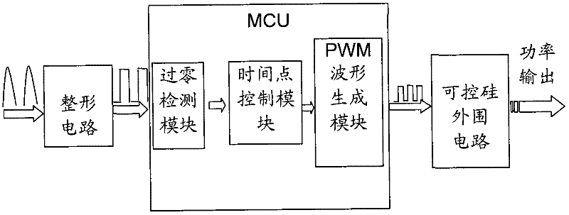
[0037] Such as image 3 Shown is a schematic diagram of the structure of the SCR zero-voltage turn-on module of the present invention. It can be seen from the figure that the turn-on module is composed of a shaping circuit, an MCU and a SCR peripheral circuit.

[0038] The shaping circuit plays the role of shaping the half-wave sine wave of the power supply into a square wave, such as Figure 4 Shown is a structural schematic diagram of the rectifying circuit in the thyristor zero-voltage turn-on module of the present invention. The rectifying circuit is a half-bridge power supply system for capacitor step-down, including a diode D1, a resistor R1, a resistor R2, a capacitor C1 and a voltage regulator tube D2, wherein the diode D1, resistor R1 and resistor R2 are connected in series, resistor R2, capacitor C1 and regulator D2 are connected in p...


PUM


Abstract

The invention relates to a controlled silicon zero-voltage turn-on module of a temperature control electric blanket and an implementation method thereof. The turn-on module consists of a shaping circuit, an MCU (microprocessor control unit) and a controlled silicon peripheral circuit. By introducing the MCU for intelligent control, the turn-on module can easily realize the detection of an alternating current zero crossing point, the control of a time point after the synchronization with a power supply electric network, and the generation of PWM (pulse width modulation) waveform, thereby realizing that controlled silicon of the electric blanket is turned on at a voltage zero-crossing point; and compared with the turn-on of the controlled silicon of the conventional electric blanket at any point of alternating voltage, the controlled silicon zero-crossing turn-on module ensures that the voltage is reduced to zero before the turn-on of the controlled silicon to eliminate the overlapping of voltage and current in the turn-on process and reduce the change rate of the voltage and the current, thereby greatly reducing even eliminating losses and switching noises, and ensuring that the temperature control electric blanket is developed in a green direction while prolonging the service life of a product.

Description

technical field [0001] The invention relates to a thyristor zero-voltage opening module, in particular to a temperature-controlled electric blanket thyristor zero-voltage opening module and a realization method thereof. Background technique [0002] Temperature-controlled electric blankets generally use thyristor as the power output switching device. The thyristor has three connection terminals: anode A, cathode K and gate (control terminal) G, such as figure 1 As shown, the cathode is the common terminal of the thyristor main circuit and the control circuit. The activation of its normal work needs to meet the following two conditions at the same time: [0003] (1) Withstand forward voltage, that is, the anode A voltage is greater than the cathode K voltage; [0004] (2) There is a trigger current at the gate; [0005] In the previous electric blanket controller, because the power switching device - the thyristor gate trigger signal did not have any time point control, it...

Claims


Application Information

Patent Timeline
Patent Type & Authority Patents(China)
IPC IPC(8): H03K17/72H05B1/02
Inventor 王冠雅李范益祝建彬
Owner BEIJING MXTRONICS CORP
Why Eureka
Try Eureka