Fresnel telescope imaging laser radar

A technology of laser radar and telescope, which is applied in the direction of instruments, measuring devices, and re-radiation, can solve the problems of low time signal transmission rate, reduce laser emission power, and difficulty in grating-like space spots, so as to improve receiving sensitivity and imaging signal. Noise ratio, reducing laser emission power, and overcoming the effects of atmospheric turbulence

Active Publication Date: 2011-02-23
SHANGHAI INST OF OPTICS & FINE MECHANICS CHINESE ACAD OF SCI
View PDF3 Cites 14 Cited by
  • Summary
  • Abstract
  • Description
  • Claims
  • Application Information

AI Technical Summary

Problems solved by technology

[0002] There are many principles for realizing imaging lidar, one of the related methods is the Fourier telescope imaging system [see literature 1, R.B.Holmes, S.Ma, A.Bhowmik, and C.Greninger, Analysis and simulation of a synthetic-aperture technique for imaging through atmospheric medium, J.Opt.Soc.Am.13(2), 351-364(1996). and literature 2, E.L.Cuellar, J.Cooper, J.Mathis, and P.Fairchild.Laboratory demonstration of a multiple beam Fourier telescopy imaging system, Proc.SPIE, 7094, 70940G-1-12, (2008).], this laser imaging radar casts grating-shaped laser spots with different orientations and different spatial frequencies to moving targets, and the targets are in motion Scanning these raster-shaped space carriers forms the space Fourier spectrum of the target, and generates a time stream signal with a lower time frequency to be received by the lidar. The target image is reconstructed by synthesizing the obtained target Fourier spectrum. Its biggest advantage is that the transmission rate of the time signal is low, so it can effectively overcome the influence of atmospheric turbulence, and allows the use of low-quality receiving optical systems, which can greatly increase the receiving optical aperture. The main problem of reducing laser emission power is that it is very difficult to realize grating-like spatial spots in various directions and spatial frequencies, so the imaging resolution is low, and multiple laser emission devices are required at the same time to make the realization device huge
[0003] There is a scanning holographic method in the field of optical holography [see literature 3, T-C. Poon, M. Wu, K. Shinoda, and Y. Suzuki. Optical scanning hologrphy, Proc. of IEEE, 84 (5): 753-764 ( 1996). And literature 4, T-C.Poon.Three-dimensional television using scanning holography, J.Information Display, 3(3):12-16(2002)], it projects a two-dimensional scanning laser interference synthesis light to the object Strongly distributed Fresnel zone plate spots, so each object point is encoded into a two-dimensional Fresnel zone plate and converted into a time stream signal, the receiving end converts the time signal into a spatial phase signal, using a spatial light modulator The image of the object is reconstructed through diffraction. This system is only suitable for stationary objects, and because the illumination uses the Fresnel zone plate spot with light intensity distribution, the receiving sensitivity and imaging signal-to-noise ratio are reduced. Acousto-optic is used in the processing. Modulation and cosine beat frequency and sine beat frequency demodulation to realize complex signal synthesis, complex electronic system

Method used


Image

  • Fresnel telescope imaging laser radar
  • Fresnel telescope imaging laser radar
  • Fresnel telescope imaging laser radar

Examples


Embodiment Construction

[0014] The present invention will be described in further detail below in conjunction with the accompanying drawings and embodiments, but the protection scope of the present invention should not be limited thereby.

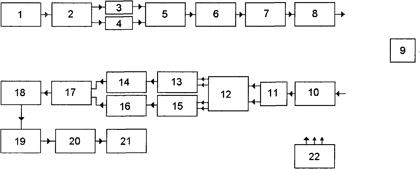
[0015] The operating principle of the Fresnel telescope imaging laser radar of the present invention is as follows figure 1 As shown, it can be seen from the figure that the Fresnel telescope imaging laser radar of the present invention is composed of a transmitting end and a receiving end, and the transmitting end includes: a laser 1, a transmitting polarization beam splitter 2, a first channel spatial phase modulator 3, a second channel Spatial phase modulator 4, transmitting polarization beam combiner 5, laser amplifier 6, transmitting telescope 7 and beam scanner 8; receiving end includes receiving telescope 10, receiving polarization beam splitter 11, 2×490° space optical bridge 12, Channel A balanced receiver 13, channel A amplifier and code-to-digital conve...


PUM


Abstract

The invention discloses a Fresnel telescope imaging laser radar, which comprises a laser, a transmitting polarization beam splitter, a first channel space phase modulator, a second channel space phase modulator, a transmitting polarization beam combiner, a laser amplifier, a transmitter-telescope, an optical beam scanner, a receiver-telescope, a receiving polarization beam splitter, a 2*4 90-degree space optical hybrid, an A-path balanced receiver and an A-path amplification and analog to digital converter, a B-path balanced receiver and a B-path amplification and analog to digital converter, a pluralizing device, a time and space coordinate converter, a resampling interpolation space coordinate converter, a matching filter and a control computer. The Fresnel telescope imaging laser radar can realize two-dimensional imaging of a target in a super optical resolution limit, improves the receiving sensitivity and imaging signal-to-noise ratio, greatly increases receiving optical aperture and reduces laser transmitting power. The optical mechanical structures and electronic equipment are simple, and the Fresnel telescope imaging laser radar is a high-resolution imaging laser radar capable of overcoming influence of atmospheric turbulence.

Description

technical field [0001] The invention relates to laser radar, especially a Fresnel telescope imaging laser radar. The principle is based on the data collection and optical and digital calculation demodulation of the target with coaxial concentric phase quadratic term polarization orthogonal double beam scanning. There are two working modes, the first one is used for moving targets, at this time the light beam scans one-dimensionally, and the second one is used for stationary targets, at this time the light beam scans two-dimensionally, and the Fresnel telescope imaging lidar can achieve super-optical resolution of the target The high-resolution two-dimensional imaging of the rate limit, due to the implementation of space-to-time transmission signal conversion and the use of coaxial coherent detection, the receiving sensitivity and imaging signal-to-noise ratio are improved, and the influence of the atmosphere on laser transmission is greatly reduced, allowing the use of The low...

Claims


Application Information

Patent Timeline
Patent Type & Authority Applications(China)
IPC IPC(8): G01S17/89G01S7/48
Inventor 刘立人闫爱民戴恩文职亚楠鲁伟吴亚鹏吕笑宇孙建锋
Owner SHANGHAI INST OF OPTICS & FINE MECHANICS CHINESE ACAD OF SCI
Why Eureka
Try Eureka