

Millimetre wave planar antenna and array thereof
A planar antenna, millimeter-wave technology, applied in antenna arrays, antennas, antenna grounding devices, etc., can solve the problems of large size, complex processing, and difficult integration of millimeter-wave antennas, achieve uniform radiation pattern, and improve antenna gain. , the effect of optimizing the overall performance
- Summary
- Abstract
- Description
- Claims
- Application Information
AI Technical Summary
Problems solved by technology
Method used
Image

Examples
Embodiment Construction
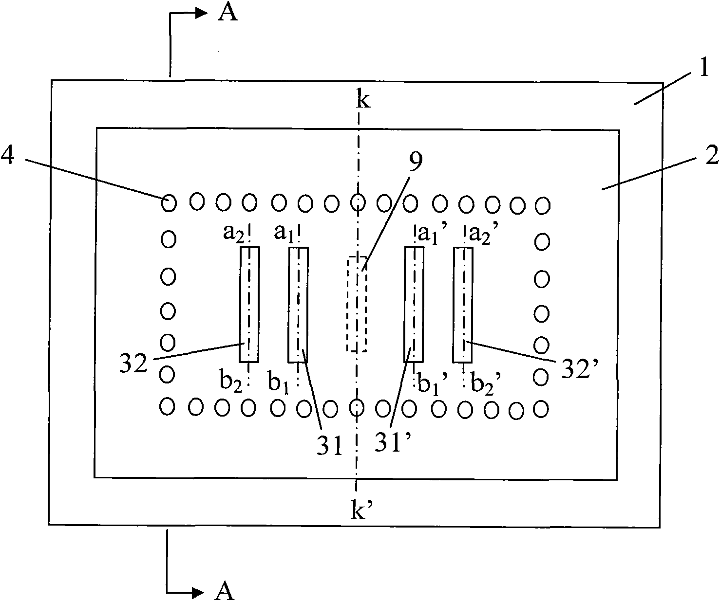
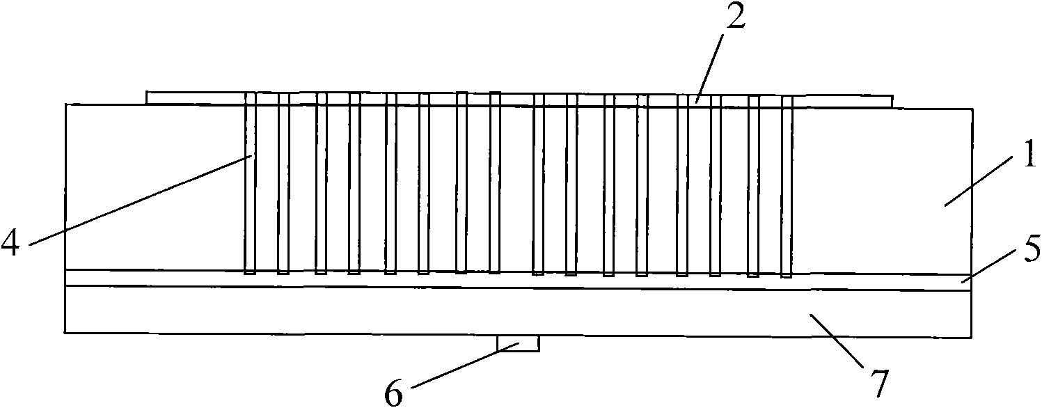
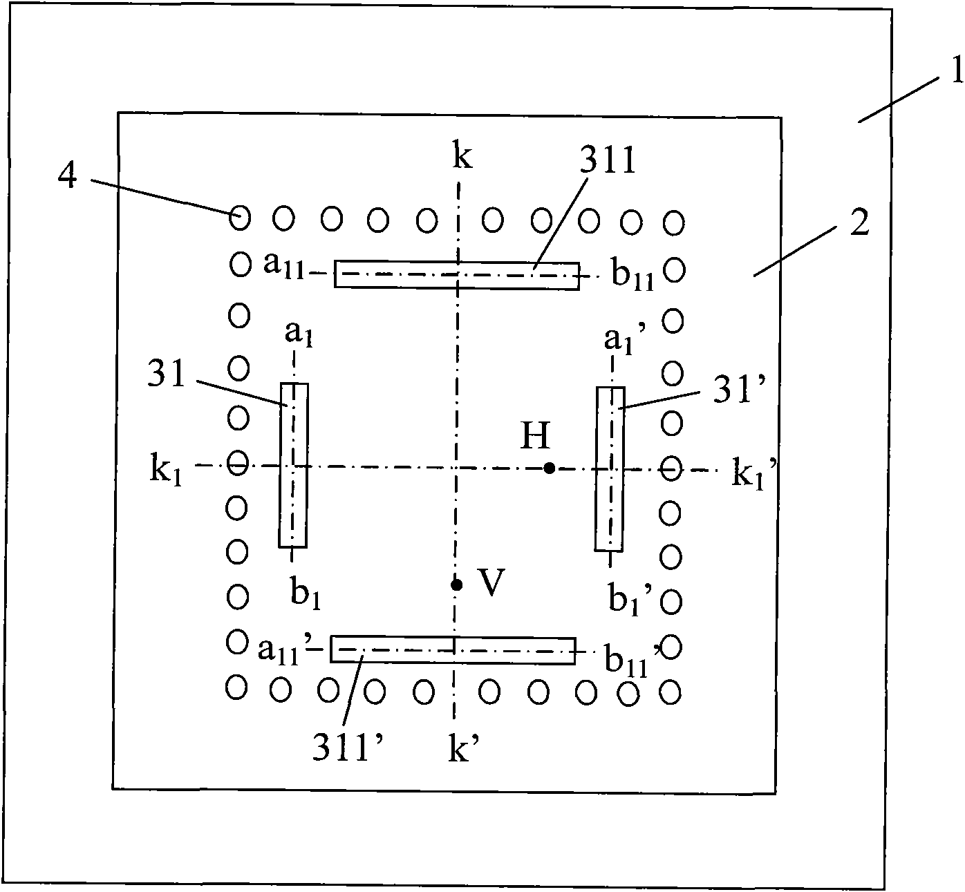
[0027] Such as figure 1 and figure 2 As shown, the millimeter-wave planar antenna of the present invention includes a metal patch 2, a dielectric substrate 1, a metal floor 5, and a ground post 4. The metal patch 2 is pasted or placed on the upper surface of the dielectric substrate 1, and the lower surface of the dielectric substrate 1 is connected to the The upper surface of the metal floor 5 is fixed. In the present invention, there are more than one pair of identical first strip-shaped grooves on the metal patch 2 . while in figure 1 In the illustrated embodiment, there are two pairs of identical first bar-shaped grooves, wherein the first bar-shaped groove 31 and the first bar-shaped groove 31' are a pair, and the other pair is the first bar-shaped groove 32 and the first bar-shaped groove 31'. The first strip groove 32'. The first strip-shaped groove 31 and the first strip-shaped groove 31' are symmetrically distributed with the straight line kk' as the center line ...
PUM
 Abstract
Description
Claims
Application Information