Energy and water saving desulphuration integrated system for power plant

An integrated system and power plant technology, applied in the field of devices in the field of heat transfer technology, can solve the problems of increasing thermal pollution of the atmospheric environment, poor economy, and large steam consumption, so as to save initial investment costs, avoid low-temperature corrosion, and save water resources Effect

Inactive Publication Date: 2011-03-30
杨本洛
View PDF8 Cites 14 Cited by
  • Summary
  • Abstract
  • Description
  • Claims
  • Application Information

AI Technical Summary

Problems solved by technology

This technical scheme once obtained people's general attention, but does not really obtain success so far
The reason is that there are obvious deficiencies: first, the heat exchanger consumes a large amount of steam, and the heat loss accounts for about 2% of the boiler efficiency, and the economy is poor; second, this method does not consider how to absorb and utilize the original flue gas before entering the desulfurization tower. Low-temperature waste heat, in order to improve the thermal efficiency of the boiler as much as possible, but also because a large amount of cooling water needs to be consumed to achieve the process requirements of reducing the temperature of the original flue gas entering the desulfurization tower, so that it will eventually cause a serious waste of water resources and increase the unnecessary pollution of the atmospheric environment. heat pollution
However, assuming that the original air preheater heat balance of the boiler leaves about 20% to 30% of the safety budget, if the device proposed here is not used, and the method provided by another patent is continued, that is, through the The above-mentioned stage III phase change heat exchanger uses the low-pressure steam extracted from the turbine exhaust port to indirectly heat the clean flue gas to achieve the same purpose of increasing the discharge temperature of the clean flue gas after desulfurization, which not only results in a relatively high initial investment in the equipment , and there are also problems of complex operation and relatively high operating costs of this part

Method used


Image

  • Energy and water saving desulphuration integrated system for power plant
  • Energy and water saving desulphuration integrated system for power plant
  • Energy and water saving desulphuration integrated system for power plant

Examples


Embodiment 1

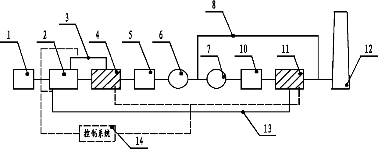
[0029]This embodiment comprises: I-stage phase-change heat exchanger 4, mixing chamber 11, control system 14, and I-stage phase-change heat exchanger 4 is placed after the air preheater 3 of boiler tail flue, is connected to mixing chamber 11 by pipeline , the mixing chamber 11 is connected to the air outlet of the air preheater 3 of the boiler system through pipelines, and the first-stage phase-change heat exchanger 4 and the mixing chamber 11 are connected to the control system 14 through wiring.

[0030] The first-stage phase-change heat exchanger 4 described in the present embodiment includes: a steam drum 101, a desalted water flow regulating valve 303, a phase-change lower section 102, and the phase-change lower section 102 is arranged in the flue after the boiler system air preheater 3. After the lower end 122 of the phase change lower section of the stage phase change heat exchanger 4, four equipments of the boiler system are sequentially connected in series: the dust c...

Embodiment 2

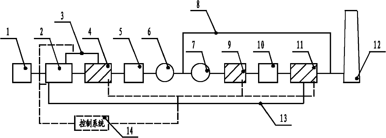
[0040] Such as figure 2 As shown, this application example further saves energy on the basis of the above-mentioned application example 1, and further improves the structure of the above-mentioned application example 1: a stage II phase-change heat exchanger is set on the flue between the desulfurization fan 7 and the desulfurization tower 10 9.

[0041] Such as Figure 5 As shown, the structure and function of the II-stage phase-change heat exchanger 9 are the same as those of the I-stage phase-change heat exchanger 4, and are divided into a phase-change lower section upper end 221 and a phase-change lower section lower end 222 by an intermediate partition plate 203, and a phase-change lower section upper end 221 It is connected to the air channel, and the lower end 222 of the phase change lower section is connected to the flue gas channel to preheat the air and boiler desalted water with the absorbed flue gas residual heat. The difference between the II-level phase-change...


PUM


Abstract

The invention discloses an energy and water saving desulphuration integrated system for a power plant in the technical field of heat transmission. The system comprises an I-level phase change heat exchanger, a mixing chamber and a control system, wherein the I-level phase change heat exchanger is arranged on the back of an air preheater arranged on a gas duct at the tail end of a boiler and then is connected with the mixing chamber through a pipeline, the mixing chamber is connected with the air outlet of the air preheater of a boiler system through a pipeline, and the I-level phase change heat exchanger and the mixing chamber are all connected with the control system through connecting wires; or an II-level phase change heat exchanger is arranged between the desulfurization fan and desulfurizing tower of the boiler system. In the invention, the phase change heat exchanger absorbs the energy of raw gas to heat clean air, and the heated clean air is mixed with the low-temperature clean gas after being further heated to a higher temperature by the air preheater, the gas outlet temperature of a chimney is increased, thus the problems of low temperature corrosion of the existing clean gas heater and invalid integral device caused by low temperature corrosion are avoided radically, the low temperature exhaust heat of the raw gas is used fully, the thermal efficiency of the integral electric generating system is improved, and meanwhile, the water resource is saved greatly.

Description

technical field [0001] The invention relates to a device in the technical field of heat transfer, in particular to an energy-saving, water-saving and desulfurization comprehensive system for power plants used for net flue gas heating up and waste heat recovery after wet desulfurization. Background technique [0002] The use of limestone wet flue gas desulfurization is a desulfurization method commonly used in large power plants. However, the use of wet lime / limestone desulfurization process (FCD) generally has severe low-temperature corrosion of the flue gas heat exchange system, which cannot heat the clean flue gas to the required temperature, and often makes the heat exchange equipment completely ineffective, eventually causing extremely serious the problem of secondary pollution. In other words, using a flue gas heater to increase the net flue gas temperature has long been a technical problem that has not been well resolved in the world. For example, according to the "T...

Claims


Application Information

Patent Timeline
Patent Type & Authority Applications(China)
IPC IPC(8): F23J15/08F23L15/00
CPCY02E20/34
Inventor 杨本洛
Owner 杨本洛
Why Eureka
Try Eureka