Cladding layer crack control method of laser surface cladding process

A control method and cladding layer technology, applied in the direction of manufacturing tools, furnaces, heat treatment equipment, etc., can solve problems such as cracks in the cladding layer, affecting the original structure of parts, and increasing repair costs

Inactive Publication Date: 2011-04-06
LIANGYI LASER TECH TIANJIN
View PDF0 Cites 13 Cited by
  • Summary
  • Abstract
  • Description
  • Claims
  • Application Information

AI Technical Summary

Problems solved by technology

However, the technology is still immature and there are still many problems to be solved
Among them, due to the large temperature gradient, narrow bonding band, and large thermal stress in the laser cladding process, cracks are easily generated in the cladding layer, and the crack problem has become a bottleneck restricting the further industrialization of this technology.
[0003] In recent years, domestic and foreign research institutions and enterprises have conducted a lot of research on the crack problem of laser cladding layer, and developed special powder materials for laser cladding, which have been better solved for the crack problem of laser cladding layer with low hardness and good toughness. Solved, but the crack problem of cladding layer with high hardness and high wear resistance is still under study
In terms of technology, the temperature difference

Method used


Image

  • Cladding layer crack control method of laser surface cladding process
  • Cladding layer crack control method of laser surface cladding process

Examples


Embodiment Construction

[0014] In order to make the object, technical solution and advantages of the present invention clearer, the implementation manner of the present invention will be further described in detail below in conjunction with the accompanying drawings.

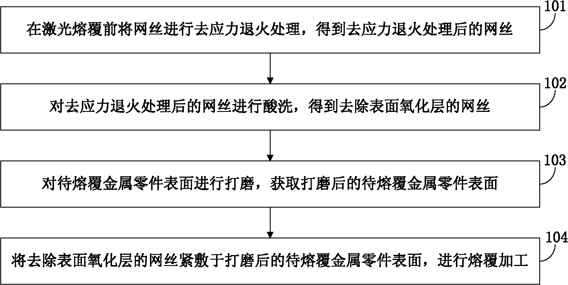
[0015] In order to suppress and eliminate cracks in the cladding layer and expand the application range of the laser cladding process, an embodiment of the present invention provides a method for controlling cracks in the cladding layer in the laser surface cladding process, see figure 1 , see the description below:

[0016] 101: Perform stress relief annealing on the mesh before laser cladding to obtain the mesh after stress relief annealing;

[0017] This step specifically includes: performing stress relief annealing on the mesh before laser cladding, removing residual stress in the mesh through stress relief annealing, and obtaining the mesh after stress relief annealing.

[0018] 102: pickling the mesh after the stress relief anne...


PUM


Abstract

The invention discloses a cladding layer crack control method of a laser surface cladding process, belonging to the field of laser surface processing and manufacture. The cladding layer crack control method comprises the following steps of: carrying out stress relief annealing processing on netting wires before the lasers are clad to obtain the netting wires subjected to the stress relief annealing processing; scouring the netting wires subjected to the stress relief annealing processing to obtain the netting wires with surface oxidation layers removed; polishing the surface of a metal part to be cladded, and acquiring the surface of the polished metal part to be clad; tightly applying the netting wires with the surface oxidation layers removed on the surface of the polished metal part to be clad, and carrying out cladding processing. The invention limits the range of crack extension, thereby realizing the purpose of crack control; in addition, the cladding layer crack control method of the laser surface cladding process is applicable to laser cladding forming and repair of metal parts, laser surface strengthening, and other related technical fields.

Description

technical field [0001] The invention relates to the field of laser surface processing and manufacturing, in particular to a method for controlling cracks in a cladding layer in a laser surface cladding process. Background technique [0002] Laser cladding is a surface coating method that changes the microstructure and composition of the surface layer of the part by adding metal elements or alloys while melting the surface of the metal part with a high-energy laser beam. According to the use requirements of the part surface, the laser cladding surface can be designed as a surface layer with different properties such as wear resistance, corrosion resistance, and oxidation resistance, and form a coating that is metallurgically bonded to the substrate and has a dense structure. Laser cladding technology can complete the repair of wear, erosion and corrosion of precision, large and valuable parts. Its application fields involve aviation, petrochemical, metallurgy, electric power ...

Claims


Application Information

Patent Timeline
IPC IPC(8): C23C24/10C21D9/00
Inventor 毛怀东
Owner LIANGYI LASER TECH TIANJIN
Why Eureka
Try Eureka