Dynamic signal demodulation method for fiber laser sensor

A dynamic signal and fiber laser technology, applied in instruments, measuring devices, measuring ultrasonic/sonic/infrasonic waves, etc., can solve problems such as being susceptible to external interference, requiring high wavelength stability, and low measurement accuracy

Active Publication Date: 2011-04-06
NANJING UNIV
View PDF6 Cites 42 Cited by
  • Summary
  • Abstract
  • Description
  • Claims
  • Application Information

AI Technical Summary

Problems solved by technology

[0010] The problem to be solved by the present invention is: the traditional optical fiber interference type dynamic sensing signal demodulation system is sus

Method used


Image

  • Dynamic signal demodulation method for fiber laser sensor
  • Dynamic signal demodulation method for fiber laser sensor
  • Dynamic signal demodulation method for fiber laser sensor

Examples


specific Embodiment approach 1

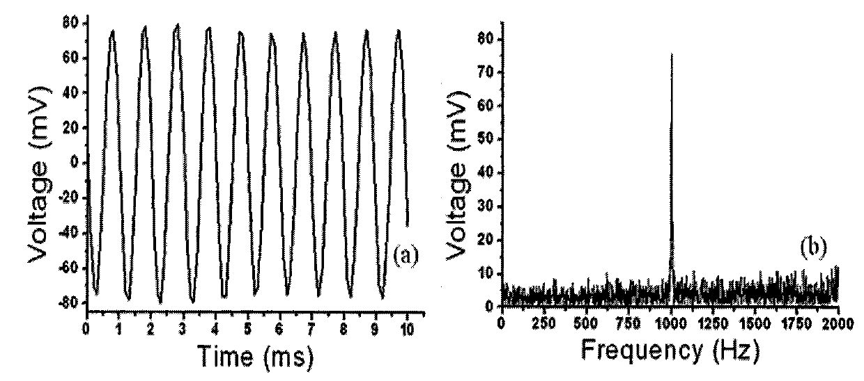
[0067] Specific embodiment 1: Utilize two fiber Bragg gratings whose central wavelength is 1549.085nm, a section of ordinary fiber with a length of 5.2m and an erbium-doped fiber with a length of 1.02m to form a resonant cavity, where the two fiber Bragg gratings are used as a multi-longitudinal mode laser The reflection mirror forms the resonant cavity of the lasing laser in the middle. The optical fiber is wound on the conformable cylinder, the conformable cylinder is fixed on the vibrating table, and the frequency and acceleration of the dynamic signal acting on the conformable cylinder can be changed by adjusting the vibrating table. image 3 It is the waveform diagram of the measured dynamic signal time domain and frequency domain, Figure 4 For an example of a measured dynamic signal, Figure 5 In order to demodulate the relationship between the system output voltage amplitude and dynamic signal acceleration.

[0068] It is also possible to fix the dual-wavelength fibe...

specific Embodiment approach 2

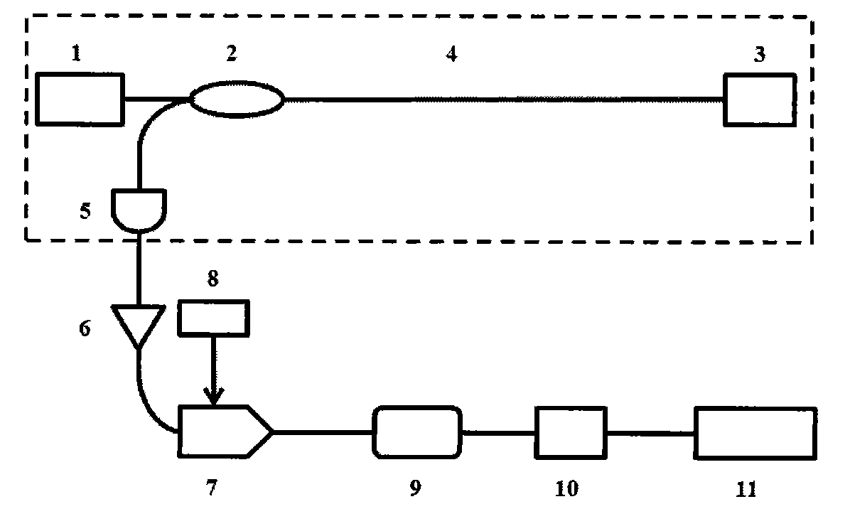
[0069] Specific implementation mode two: as Image 6 As shown, multi-longitudinal-mode fiber laser sensing probes, dual-wavelength fiber laser sensing probes or polarized fiber laser sensing probes are connected in series to form sensing probe arrays 3-1, 3-2...3-n, and the entire multiplexing system Among them, the multi-longitudinal-mode fiber optic sensor laser probe, the dual-wavelength fiber laser sensor probe and the polarization fiber laser sensor with different central wavelength and beat frequency signals should be selected, because each sensor probe has its own unique beat frequency signal , by adjusting the frequency of the intrinsic signal 8, the carrier frequency of the beat frequency signal generated by a sensing probe can be down-converted to the carrier frequency f matched by the FM demodulator 9 through the mixer 7 c , so that the demodulation and detection of multi-point distributed dynamic sensing signals can be realized by means of wavelength division multi...


PUM

PropertyMeasurementUnit
Lengthaaaaaaaaaa
Lengthaaaaaaaaaa

Abstract

The invention discloses a dynamic signal demodulation method for a fiber laser sensor. A sensing system is established, and comprises a beat frequency signal generation part and a signal demodulation part. The beat frequency signal generation part generates a beat frequency signal and receives a dynamic signal through a sensing probe; the original beat frequency signal is demodulated into a frequency modulation (FM) signal by the dynamic signal; the FM signal is input into the signal demodulation part and demodulated by an FM demodulator to form a modulation signal, namely, the dynamic signal; and the modulation signal is subject to analogue-digital (AD) conversion through an AD data acquisition card and then processed by a digital processing circuit to obtain the frequency and acceleration parameters of the dynamic signal. Through the invention, the dynamic signal demodulation method is free from influence of light-intensity variation, electromagnetic interference and the like; and compared with the known fiber dynamic demodulation method, the dynamic signal demodulation method is easy to implement and ensures stable and reliable operation and low cost.

Description

technical field [0001] The invention belongs to the technical field of optical fiber sensing system and signal demodulation. It is related to fiber optic sensors, fiber Bragg gratings, dual-wavelength fiber lasers, polarization fiber lasers, FM demodulation technology, etc., involving signal conditioning, signal processing, etc., and is widely used in the measurement of various dynamic physical quantities. The dynamic demodulation method of fiber laser sensor is a new technology to demodulate the sensing information of dynamic sensors with beat-frequency output such as dual-wavelength type, multi-longitudinal model, and polarization type. Background technique [0002] Optical fiber sensors have the advantages of anti-electromagnetic interference, corrosion resistance, intrinsic safety, small size, light weight, strong anti-interference ability, wavelength coding, and easy multiplexing and networking. It can be used to measure physical information such as strain, temperature,...

Claims


Application Information

Patent Timeline
IPC IPC(8): G01D3/028G01H9/00
Inventor 高亮刘盛春陈向飞殷作为
Owner NANJING UNIV
Why Eureka
Try Eureka