Low temperature SCR moving bed flue gas denitration method for coal-fired boiler

A coal-fired boiler and moving bed technology, applied in separation methods, chemical instruments and methods, dispersed particle separation, etc., can solve problems such as difficulty in achieving sulfur resistance and water resistance, and achieve low space requirements, high denitration performance, and wide The effect of the application foreground

Inactive Publication Date: 2011-04-13
GUODIAN SCI & TECH RES INST +1
View PDF3 Cites 29 Cited by
  • Summary
  • Abstract
  • Description
  • Claims
  • Application Information

AI Technical Summary

Problems solved by technology

Therefore, it is difficult to achieve the performance of sulfur resistance and water resistance only by the ca

Method used


Image

  • Low temperature SCR moving bed flue gas denitration method for coal-fired boiler
  • Low temperature SCR moving bed flue gas denitration method for coal-fired boiler
  • Low temperature SCR moving bed flue gas denitration method for coal-fired boiler

Examples


Embodiment 1

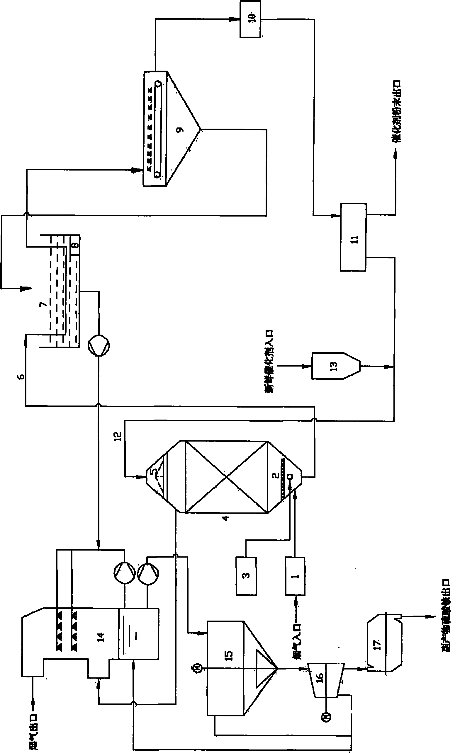
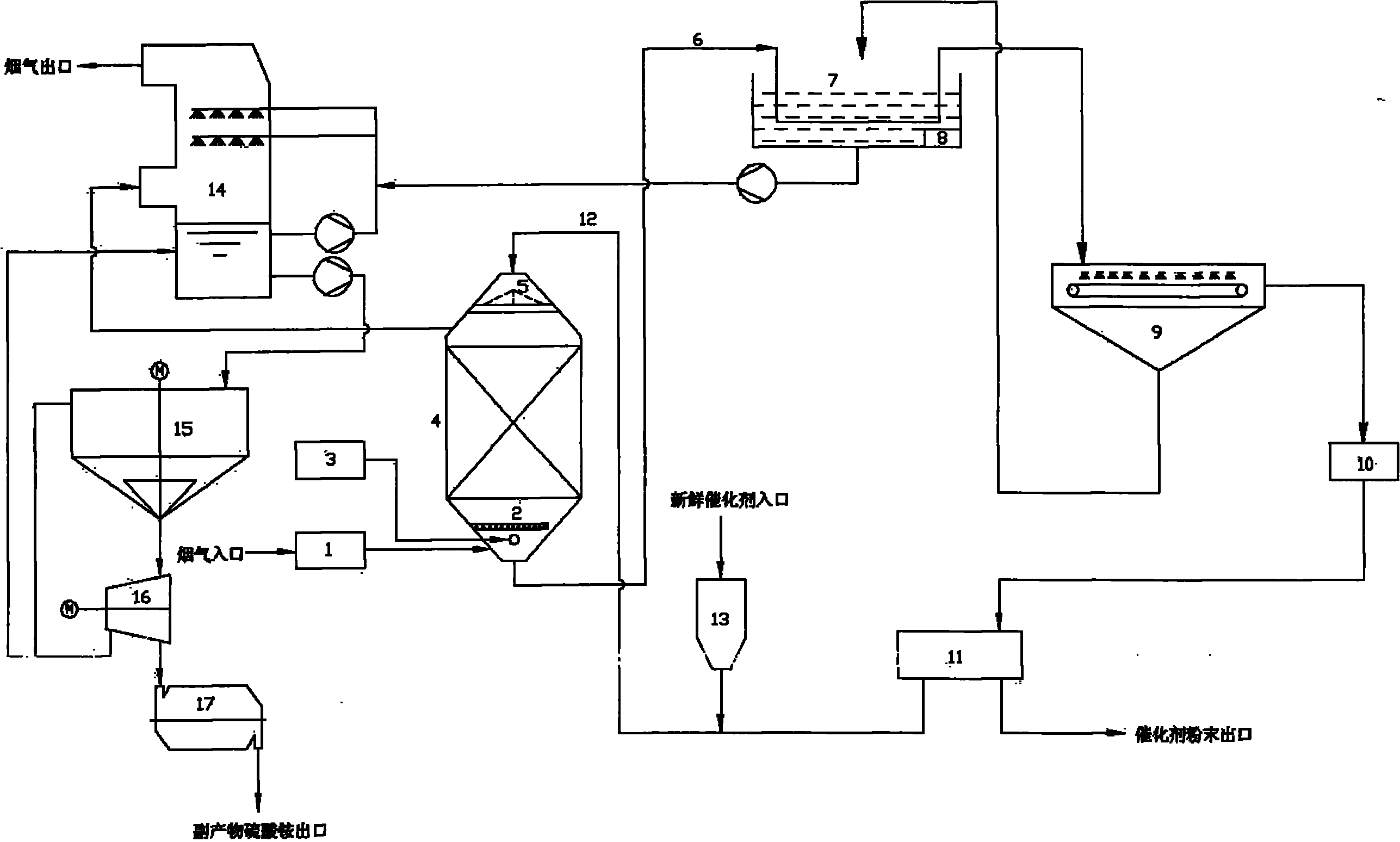
[0020] A power station boiler exhausts 500,000 m of flue gas 3 / h, the concentration of sulfur dioxide in the flue gas is 2000mg / Nm 3 , the concentration of nitrogen oxides is 600mg / Nm 3 , The design diameter of the denitrification reactor is 8 meters, the height is 20 meters, and the catalyst with a particle size of 2.5-7.5 mm is selected, and the total circulation is 200 tons. The specific process is:

[0021] The temperature of the flue gas from the boiler is 125°C. The flue gas enters the moving bed denitrification reactor 4 after passing through the dust collector 1, and 150 tons of granular catalysts are preset in the reactor; the flue gas passes through the gas distributor 2 and is connected with the ammonia generator 3 The ammonia gas is mixed and contacted, the added NH 3 The molar ratio of NOx to the flue gas is 1:1, and the mixture enters the catalytic layer together with the latter, and the flue gas from which NOx has been removed is discharged from the upper pa...

Embodiment 2

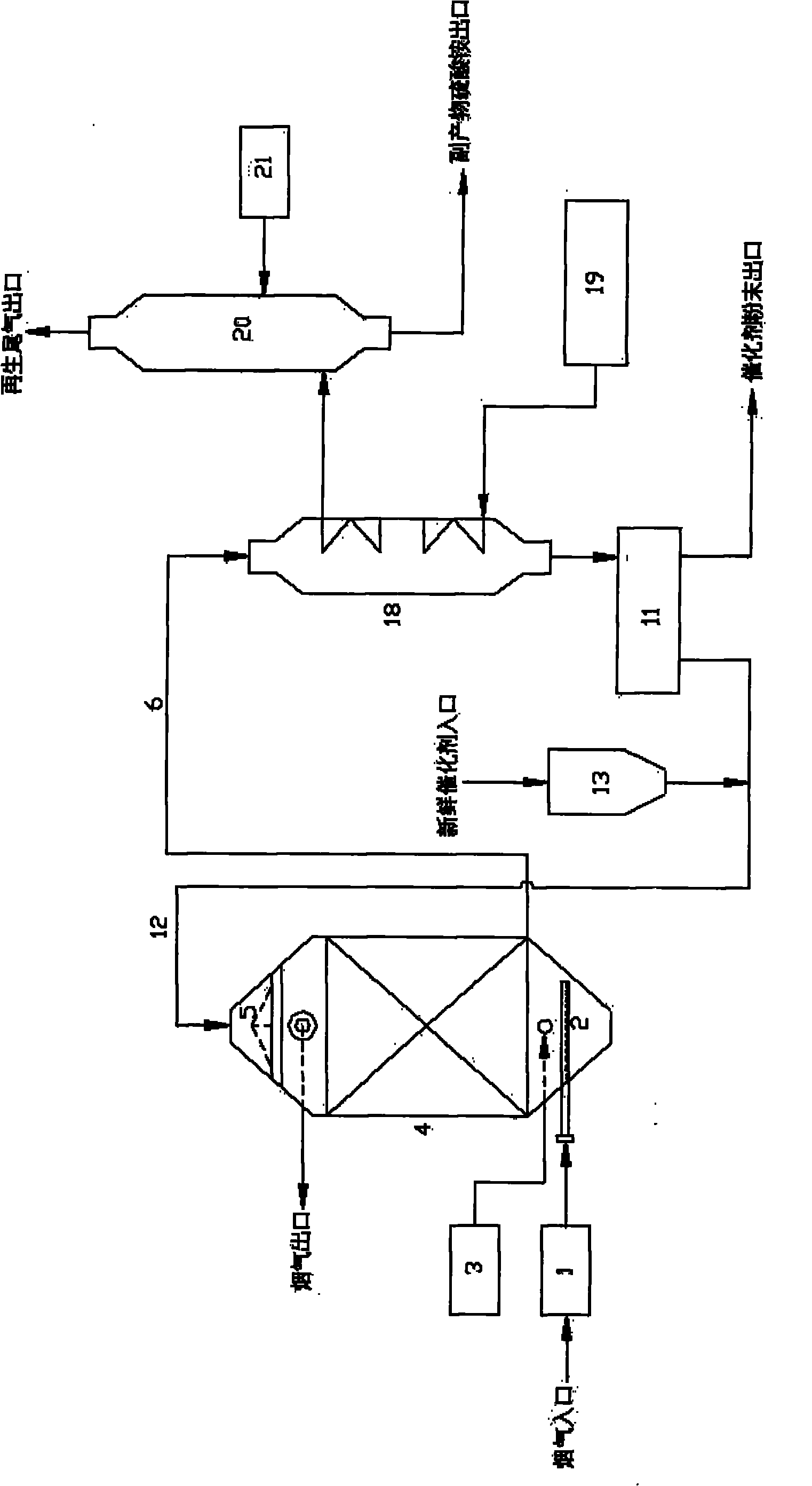
[0024] A power station boiler exhausts 1.2 million m3 of flue gas 3 / h, the concentration of sulfur dioxide in the flue gas is 1500mg / Nm 3 , the concentration of nitrogen oxides is 450mg / Nm 3 , The denitrification reactor is designed with a diameter of 10 meters and a height of 25 meters. The catalyst with a particle size of 2.5 to 7.5 mm is selected. The shape of the catalyst is granular, short columnar or honeycomb, etc. The total circulation is 400 tons. The specific process is:

[0025] Such as figure 2 , the flue gas temperature from the boiler is 130°C, the flue gas enters the moving bed denitrification reactor 4 after passing through the dust collector 1, and 300 tons of short columnar catalysts are preset therein. The flue gas passes through the gas distributor 2, mixes and contacts with the ammonia gas from the ammonia generator 3, and the added NH 3 The molar ratio to NO in the flue gas is 1:1. After mixing evenly, it enters the catalytic layer together, and the...


PUM


Abstract

The invention relates to a low temperature selective catalytic reduction (SCR) moving bed flue gas denitration method for a coal-fired boiler. Boiler flue gas subjected to dust removal and a denitration reducer NH3 are introduced into a denitration reactor respectively; a low temperature SCR catalyst is continuously input from one end of the denitration reactor and continuously output from the other end of the denitration reactor to form a moving bed; the flue gas and the NH3 are in gas-solid contact with the catalyst which moves directionally in a countercurrent or crosscurrent mode in the reactor; NOx and NH3 in the flue gas are reacted with each other and the generated N2 and water vapor are discharged out of the denitration reactor along with the denitrified flue gas; in the process, parts of SO2 and NH3 in the flue gas are reacted with each other and the generated sulfate is deposited on the catalyst; and an inactivated catalyst which is continuously output from the denitration reactor enters a regenerative process, the regenerated catalyst returns to the reactor and the steps are continuously and repeatedly circulated by the method. By continuously regenerating the catalyst, the method solves the problem of catalyst poisoning and improves the denitration efficiency and running stability of a system.

Description

technical field [0001] The invention belongs to the field of air pollution control, and in particular relates to a method and a system for flue gas denitrification of a low-temperature SCR moving bed of a coal-fired boiler. Background technique [0002] In my country's primary energy, the proportion of coal consumption is more than 70%, so coal is the main source of energy in our country. NOx produced during coal combustion is followed by SO 2 It is one of the important air pollutants that need to be treated urgently. In order to protect the environment and realize the sustainable development of human beings, countries around the world have formulated strict environmental protection regulations, such as the United States, Japan, Germany, etc., have formulated strict emission standards for nitrogen oxides, and stipulated strict implementation reduction plans. With the promulgation of the domestic "Nitrogen Oxide Prevention and Control Technology Policy for Thermal Power Pla...

Claims


Application Information

Patent Timeline
IPC IPC(8): B01D53/90B01D53/56
Inventor 王忠渠刘健民曹沂胡宇峰王小明薛建明盛重义
Owner GUODIAN SCI & TECH RES INST
Why Eureka
Try Eureka