Dissimilar metal spot welding system of light metal and coated steel and welding method thereof

A technology of coated steel plates and dissimilar metals, applied in welding equipment, metal processing equipment, arc welding equipment, etc., can solve problems such as joint deformation, reduce vehicle body design and manufacturing costs, and achieve low cost, easy promotion and application, and superior mechanical properties Effect

Active Publication Date: 2011-05-11
SHANGHAI JIAO TONG UNIV +1
View PDF4 Cites 43 Cited by
  • Summary
  • Abstract
  • Description
  • Claims
  • Application Information

AI Technical Summary

Problems solved by technology

[0005] Aiming at the above-mentioned deficiencies in the prior art, the present invention provides a dissimilar metal spot welding system and welding method for light metal and coated steel plate. By forming a spot fusion brazing joint between light metal and coated steel plate, the spot welding of light metal and steel is realized. C

Method used


Image

  • Dissimilar metal spot welding system of light metal and coated steel and welding method thereof
  • Dissimilar metal spot welding system of light metal and coated steel and welding method thereof
  • Dissimilar metal spot welding system of light metal and coated steel and welding method thereof

Examples


Embodiment 1

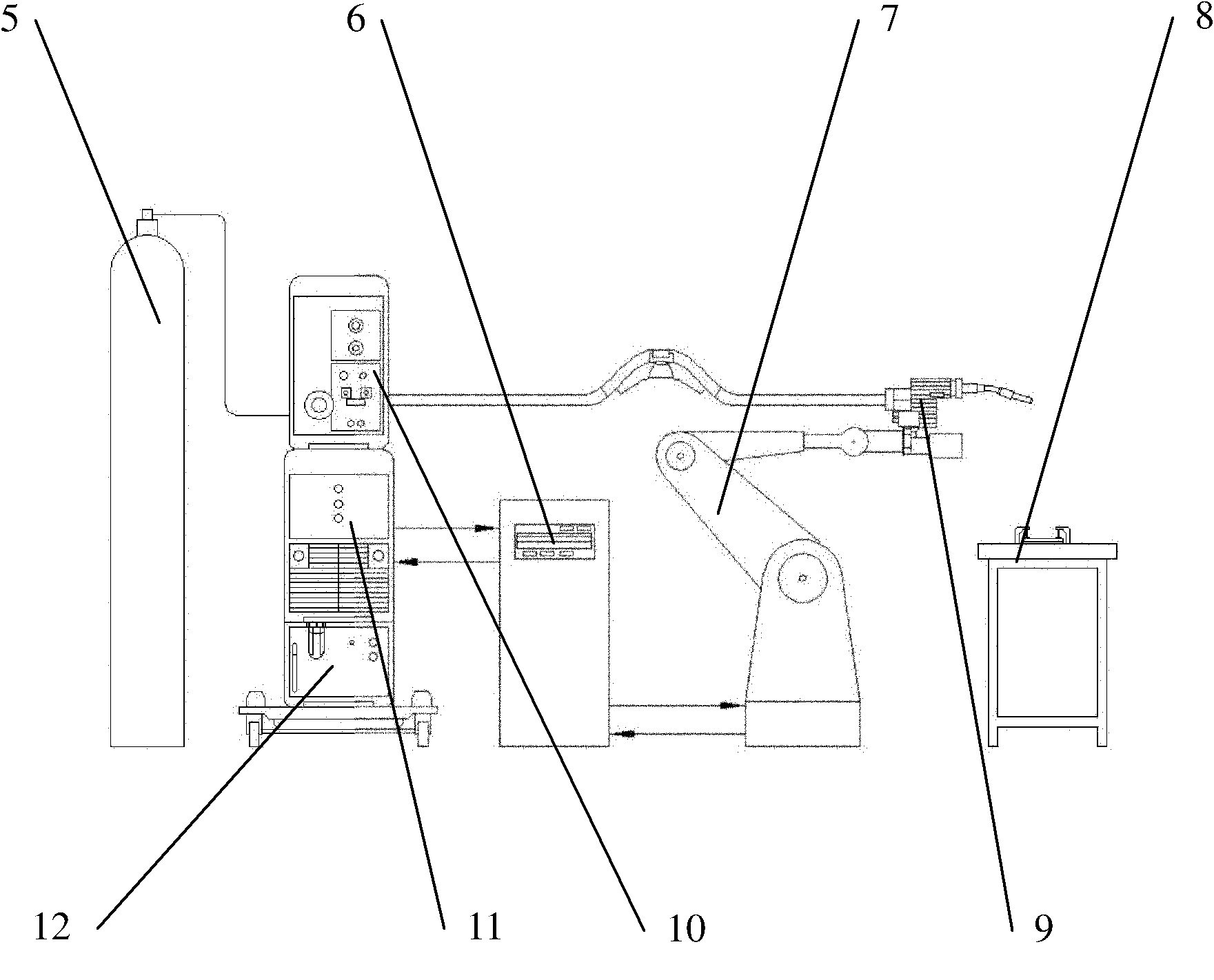
[0029] Such as figure 2 As shown, this embodiment includes: CMT arc welding system 1, welding wire 2, perforated light metal plate 3, steel plate 4, gas cylinder 5, robot control module 6, robot 7, and clamping device 8. Among them: the CMT arc welding system 1 is connected to the robot control module 6 and transmits welding control signals, the welding wire 2 is installed in the CMT arc welding system 1, the perforated light metal plate 3 and the steel plate 4 are fixed on the clamping device 8, and the gas cylinder 5 and The CMT arc welding system 1 is connected, and the robot control module 6 is connected with the robot 7 to transmit control signals for the movement of the robot 7.

[0030] The CMT arc welding system includes: a welding gun 9, a wire feeder 10, a host power supply 11, and a coolant tank 12. The welding gun 9 is connected to the wire feeder 10, the host power supply 11 and the coolant tank 12, and is installed in the robot The end of the 7; the wire feeder 10 ...

Embodiment 2

[0047] The upper light metal plate 3 of this embodiment is aluminum alloy AA6061-T6, and the lower galvanized steel plate 4 is high-strength steel DP780. The thickness of the plate is matched: 1mm+2mm, the hole diameter is 6.5mm, and the center distance between the holes is 20mm. The aluminum alloy plate 3 is mechanically polished to remove the oxide layer on the surface, and an acetone reagent is used to remove oil stains on the surface of the metal plate.

[0048] Process parameters: Welding wire 2 material is A1Si5, diameter is 1.2mm, welding current is 144A, voltage is 16.4V, wire feeding speed is 6.5m / min, arc length is corrected to -30%, wire withdrawal frequency is 70Hz, and argon gas is used as protection Gas, the flow rate is 15L / min, and the welding time is 0.8s.

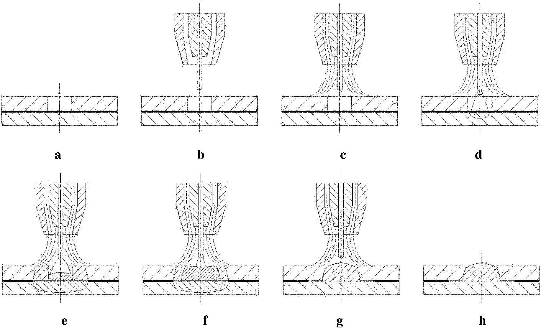
[0049] The technological process of this embodiment is as follows image 3 (a)~(h) and Figure 4 Shown:

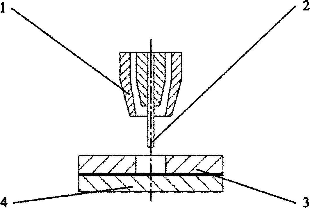
[0050] 1) Pre-drill a number of process holes with a cylindrical diameter of 6.5mm in the aluminum alloy...


PUM

PropertyMeasurementUnit
Coating thicknessaaaaaaaaaa
Diameteraaaaaaaaaa

Abstract

The invention provides a dissimilar metal spot welding system of light metal and coated steel and a welding method thereof, wherein the system comprises a CMT (cold metal transfer) arc welding system, an air bottle, a robot control module, a robot and a clamping device; the arc welding system is connected to the robot control module and used for transmitting a welding control signal; the air bottle is communicated with the CMT arc welding system; the robot control module is connected to the robot for transmitting a control signal of the movement of the robot. In the invention, a spot melting soldering joint is formed between light metal and coated steel to realize the spot connection of the light metal and the coated steel; the serious deformation of the joint during continuous seam welding is solved while the connecting quality of dissimilar metal is ensured; traditional vehicle body part joints primarily using resistance spot welding process are not influenced; and the design and manufacture costs of vehicle bodies are greatly reduced.

Description

Technical field [0001] The invention relates to a device and method in the technical field of metal welding, in particular to a dissimilar metal spot welding system and a welding method for light metals and coated steel plates. Background technique [0002] Because the density of light alloy materials such as aluminum and magnesium is much smaller than that of steel, they are favored by major automobile manufacturers. However, the overall mechanical properties of advanced steel are still better than that of light alloy materials, so the multi-material connection of light alloy and advanced high-strength steel is adopted. The structure has become the first choice for lightweight vehicles, which involves the heterogeneous connection between light alloy and steel. [0003] Because of the huge difference in melting point, thermal expansion coefficient and electrical conductivity between aluminum and steel, and the easy formation of hard and brittle phases-intermetallic compounds during...

Claims


Application Information

Patent Timeline
IPC IPC(8): B23K9/007B23K9/23B23K9/235B23K9/173
Inventor 李永兵林忠钦雷海洋王培中来新民陈关龙
Owner SHANGHAI JIAO TONG UNIV
Why Eureka
Try Eureka