Electrodeless fluorescent lamp

A technology for electrodeless fluorescent lamps and lamp tubes, which is applied in the direction of discharge lamps, parts of gas discharge lamps, electrical components, etc., which can solve the problems of reducing the amount of fluorescent light, increasing the temperature of magnets, and conducting interference, and achieving the reduction of bridging and sealing. process, reduce the temperature of the coupler, and have a wide range of applications

Inactive Publication Date: 2012-08-22
SHANGHAI YUANMING LIGHTING TECH
View PDF4 Cites 0 Cited by
  • Summary
  • Abstract
  • Description
  • Claims
  • Application Information

AI Technical Summary

Problems solved by technology

With the increase of the power-on working time, a large amount of heat generated on the magnet will cause the temperature of the magnet to rise sharply, thereby reducing the performance of the magnet and increasing the eddy current loss, thereby reducing the energy of the high-frequency electromagnetic field in the bulb and reducing the amount of fluorescence (that is, reducing the lamp's brightness) working power, reducing luminous flux), especially when the lamp tube and ballast are installed in the airtight lamp, the heat on the magnet cannot be dissipated in time, until the Curie temperature of the magnet is exceeded, the magnet will lose its function and stop the lamp work or malfunction
[0009] Since the ballast adopts a driving frequency of 100-300KHz, although it is one-tenth of the high-frequency electrodeless lamp (2.65M), there is also serious EMC (electromagnetic compatibility) conduction interference, and the radiation of the lamp tube is large, which not only causes damage to the power grid Harm, and pose a threat to its own reliable operation, the scope of application is greatly limited
[0010] In addition, the current technical solutions of many electrodeless lamps basically start with the structure of the lamp tube, the shielding and heat dissipation of the magnetic ring, etc., and do not start with the convenient (surface) matching of the electrodeless lamp with the existing lamps. When some lamps are replaced with electrodeless lamps, due to the mismatch between the reflector of the lampshade and the light distribution of the bulb, resulting in uneven illuminance or the replacement of a whole set of lamps at the same time, it also brings unfavorable factors such as waste of resources. The application range of electrodeless lamps is very limited; this requires an electrodeless lamp that can easily adjust the light distribution without replacing the original lamps, so that the original lamps can be used without wasting Achieve uniform light distribution, and easy to replace and install, to meet the needs of the market

Method used


Image

  • Electrodeless fluorescent lamp
  • Electrodeless fluorescent lamp
  • Electrodeless fluorescent lamp

Examples


Embodiment 1

[0074] see Image 6 with Figure 7 , the whole lamp tube includes two U-shaped glass lamp tubes 600 and 700 welded together, three primary color phosphors 2 are attached to the inner tube walls of the glass lamp tubes 600 and 700, and the two ends of the glass lamp tube 600 are bent into the second A sensing surface 610 and a second sensing surface 620. An exhaust glass tube 650 is arranged in the glass lamp tube 600. The exhaust glass tube 650 is also used to place the indium mesh 660, corresponding to the first sensing surface 610 and the second sensing surface 620. There is a first welding surface 630 and a second welding surface 640 . The two ends of the glass lamp tube 700 are bent into a third sensing surface 710 and a fourth sensing surface 720, a bent glass tube 750 is arranged inside the glass lamp tube 700, an amalgam 760 is placed inside the bent glass tube 750, and the bent The glass tube 750 can prevent the amalgam 760 from flowing backward, and the third sensin...

Embodiment 2

[0077] see Figure 8 , the whole lamp tube is composed of a U-shaped glass lamp tube 600, three primary color phosphors 2 are attached to the inner tube wall of the glass lamp tube 600, and exhaust glass tubes 650 and folding Bent glass tube 750, an induction body 830 is arranged between the two ends of the glass lamp tube 600, the exhaust glass tube 650 is used to place indium mesh 660 at the same time, amalgam 760 is placed in the bent glass tube 750, and the bent glass tube 750 It can prevent the amalgam 760 from flowing backward. A power coupler (not shown in the figure) is installed on the inductor 830 . In order to maintain sufficient power of the lamp when the lamp works at low temperature for a long time, a thermal sleeve 761 is placed on the amalgam 760 of the bent glass tube 750, so that the power will be stable when the lamp works at low temperature for a long time.

Embodiment 3

[0079] see Figure 9 , the whole tube consists of a semi-curved Type 600 glass tube and a semi-bent inverted Type glass lamp tube 700 is welded, on the inner wall of the glass lamp tubes 600 and 700, three primary color phosphors 2 are attached, and the two ends of the glass lamp tube 600 are bent into a first sensing surface 610 and a second sensing surface 620 There is an exhaust glass tube 650 inside the glass lamp tube 600, the exhaust glass tube 650 is also used to place the indium mesh 660, and the welding surfaces corresponding to the first sensing surface 610 and the second sensing surface 620 are flat. The two ends of the glass lamp tube 700 are bent into a third sensing surface 710 and a fourth sensing surface 720, a bent glass tube 750 is arranged inside the glass lamp tube 700, an amalgam 760 is placed inside the bent glass tube 750, and the bent The glass tube 750 can prevent the amalgam 760 from flowing backward, and the welding surfaces corresponding to the th...


PUM


Abstract

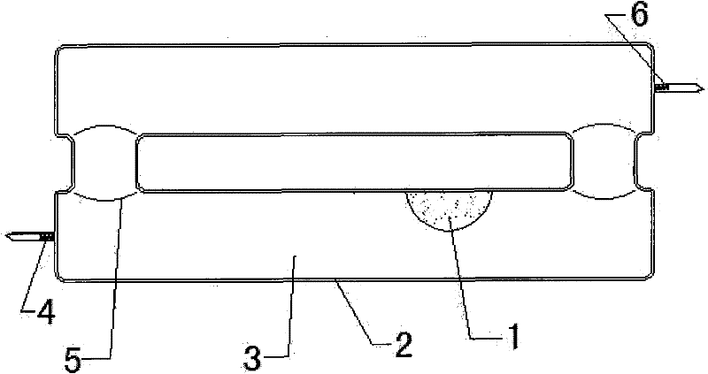
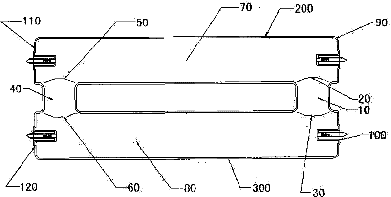
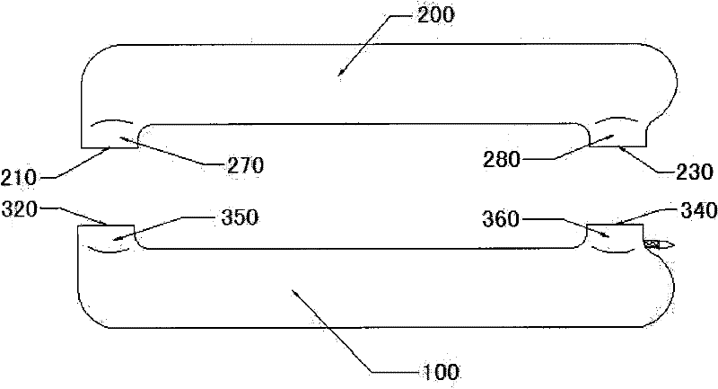
The invention discloses an electrodeless fluorescent lamp, which comprises a lamp tube, a lamp, power couplers coupled at both ends of the lamp tube and a ballast electrically connected with the power couplers, wherein mixed gas is filled into the lamp tube. The electrodeless fluorescent lamp is characterized in that: the power coupler is in heat conducting connection with the lamp, so that the integral lamp or a lamp shade is a radiating device of the coupler; and a U-shaped groove or a V-shaped groove is formed on a heat conducting plane to increase a heat conducting area further. In the electrodeless fluorescent lamp, a gas structure is changed, the structure of a glass lamp tube is simplified, and the bridging and sealing-in process is saved; and due to the adoption of the proportioning of the gas, the problem that an electrodeless lamp (the electrodeless fluorescent lamp) is difficult to start in high-power lamp tubes with long loops and thin tube diameters is solved, and the low-temperature starting performance of lamp bulbs is improved.

Description

Technical field: [0001] The invention relates to an electrodeless fluorescent lamp, also known as an electrodeless fluorescent lamp, in particular to an electrodeless fluorescent lamp which can be installed in a closed lamp and can be started instantaneously in a low temperature environment. Background technique: [0002] Use radio frequency, radio frequency or microwave wave energy to excite mercury vapor in fluorescent lamps, make the outer electrons of mercury atoms gain energy and emit ultraviolet photons, which are absorbed by the phosphor powder coated on the lamp wall to emit visible light. Electrodeless fluorescent lamps were successfully tested in the early 1990s and put on the market in the middle and late 1990s. Because of their good spectral continuity, no flicker when starting, and large fluctuations in power supply voltage, they have been praised as the best by the lighting circles of various countries. Green electric light source. [0003] As early as 1970, J...

Claims


Application Information

Patent Timeline
Patent Type & Authority Patents(China)
IPC IPC(8): H01J65/04H01J61/52H01J61/56H01J61/24H01J61/30H01J61/12
Inventor 叶际爽叶胜
Owner SHANGHAI YUANMING LIGHTING TECH
Why Eureka
Try Eureka