Double-fluid injector

A dual-fluid, ejector technology, applied in liquid ejection devices, ejection devices, ejection devices, etc., can solve the problems of not considering the fluid, inconsistent size of glue points, different responses, etc., and achieve long service life, convenient operation and simple structure. Effect

Active Publication Date: 2011-05-25
SHANGHAI UNIV
View PDF5 Cites 10 Cited by
  • Summary
  • Abstract
  • Description
  • Claims
  • Application Information

AI Technical Summary

Problems solved by technology

The pneumatic glue dispensing technology is that the high-pressure gas directly acts on the glue or the piston to realize the glue injection, but in this technology, as the dispensing progresses, the remaining glue volume in the glue barrel is different, it The response to high-pressure gas with the same pressure and flow rate is different, resulting in inconsistent glue point sizes
The above technologies do not consider the characteristics of the fluid itself, such as the movement characteristics of the fluid in the microchannel, so there will be various defects and limitations in the realization of the non-contact glue distribution technology

Method used


Image

  • Double-fluid injector
  • Double-fluid injector
  • Double-fluid injector

Examples


Embodiment 1

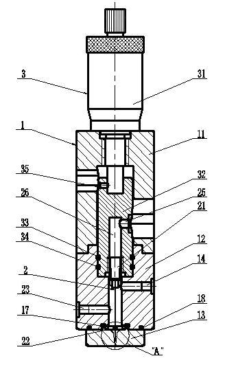
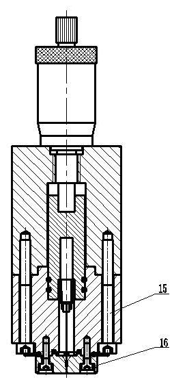
[0037] refer to figure 1 and figure 2 , the dual-fluid injector includes a valve body (1), an injection mechanism (2), and a stroke adjustment mechanism, and is characterized in that: the valve body (1) is fixedly connected to the upper valve body by the upper and lower ends of the middle valve body (12) (11) and the lower valve body (13); the stroke adjustment mechanism is placed in the inner cavity formed between the middle valve body (12) and the upper valve body (11), and the stroke adjustment mechanism is a differential head stroke adjustment Mechanism (3); the dual-fluid injection mechanism (2) is arranged in the inner cavity formed between the middle valve body (12), the lower valve body (13) and the differential head stroke adjustment mechanism (3).

Embodiment 2

[0039] This embodiment is basically the same as Embodiment 1, and the special features are as follows:

[0040]The differential head stroke adjustment mechanism (3) includes a differential head (31), a needle valve (32), O-rings (33, 34) and set screws (35); it is characterized in that: the differential head (31 ) at the installation position, the external thread is screwed with the internal thread on the upper end of the upper valve body (11) to realize the fixed connection between the differential head (31) and the valve body (1), the end of the differential head (31) and the top of the needle valve (32) The countersunk head fits and is fixedly connected by the side wall set screw (35); O-rings (33, 34) are arranged between the side wall of the needle valve (32) and the middle valve body (12) to realize the needle valve (32) and the seal between the middle valve body (12).

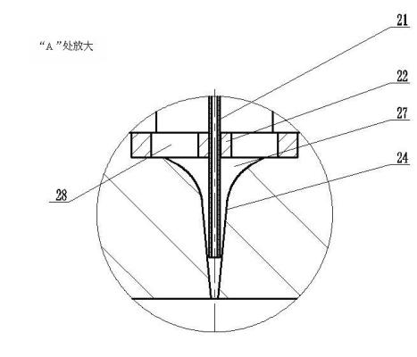
[0041] refer to image 3 , the dual-fluid injection mechanism (2) includes a gas needle (21), a gui...


PUM


Abstract

The invention relates to a double-fluid injector, which comprises a valve body, an injection mechanism and a travel adjusting mechanism, wherein the valve body consists of an upper valve body and a lower valve body which are fixedly connected to the upper end and the lower end of a middle valve body respectively; the travel adjusting mechanism is arranged in a cavity formed between the middle valve body and the upper valve body and is a micrometer head travel adjusting mechanism; and the injection mechanism is arranged in a cavity formed among the middle valve body, the lower valve body and the travel adjusting mechanism and is a double-fluid injection mechanism. The flow forms of double fluids in a mixing cavity are controlled by adjusting the flows and pressures of input gas and liquid,so that liquid is sprayed from a nozzle on the lower valve body in dot, line and mist forms. The double-fluid injector has a simple structure, long service life, high gas and liquid controllability, high injection accuracy and high working frequency, and can be applied to multi-fluid injection processes in preparation of semiconductor membranes, preparation of composite materials, electronic encapsulating, (MENS) systems, ink jet, spraying, lubrication, powder metallurgy, food processing, biomedicine, welding, rapid prototyping manufacturing, combustion, engines, chemical industry and the like.

Description

technical field [0001] The invention relates to a dual-fluid injector, in particular to an injection structure for high-precision injection. It can produce high-frequency, high-precision and controllable liquid point, line and atomized spray effects. It can be widely used in semiconductor film preparation, composite material preparation, electronic packaging, MENS system, inkjet, spray coating, lubrication, powder metallurgy, food processing, biomedicine, welding, rapid prototyping, combustion, engine, chemical industry and other multi-fluid processes jetting process. [0002] Background technique [0003] In the semiconductor packaging industry, glue distribution technology is one of the key technologies, and it is widely used in chip mounting, chip coating, thermal silica gel filling, chip and substrate interconnection and other processes. The development of glue dispensing technology has successively produced a large number of mass dispensing, contact dispensing, and n...

Claims


Application Information

Patent Timeline
Patent Type & Authority Applications(China)
IPC IPC(8): B05B7/04B05B7/12B05B1/12B05B15/00
Inventor 张金松彭鹏王志亮张建华
Owner SHANGHAI UNIV
Why Eureka
Try Eureka