Peak load power generation device

A peak load and power generation device technology, applied in steam engine devices, jet propulsion devices, gas turbine devices, etc., can solve problems such as equipment wear, increased power generation costs, and pollutant emissions, and achieve efficient recycling and utilization, efficient capture and storage, The effect of reducing environmental pollution

Inactive Publication Date: 2011-06-22
丁玉龙
View PDF7 Cites 21 Cited by
  • Summary
  • Abstract
  • Description
  • Claims
  • Application Information

AI Technical Summary

Problems solved by technology

As a flexible composite power generation technology, although the system can adjust the balance of supply and demand, it also has its inherent defects: one is that it is easy to cause waste of excess electric energy or thermal power system sub-load operation in the valley section where the demand is lower than the average load. Second, the high idle rate of peak power generation devices will reduce the overall economic benefits; Third, high-cost fuels such as oil or natural gas will increase the overall cost of power generation

Method used


Image

  • Peak load power generation device
  • Peak load power generation device

Examples


Embodiment Construction

[0022] The preferred embodiments of the present invention will be described below in conjunction with the accompanying drawings. It should be understood that the preferred embodiments described here are only used to illustrate and explain the present invention, and are not intended to limit the present invention.

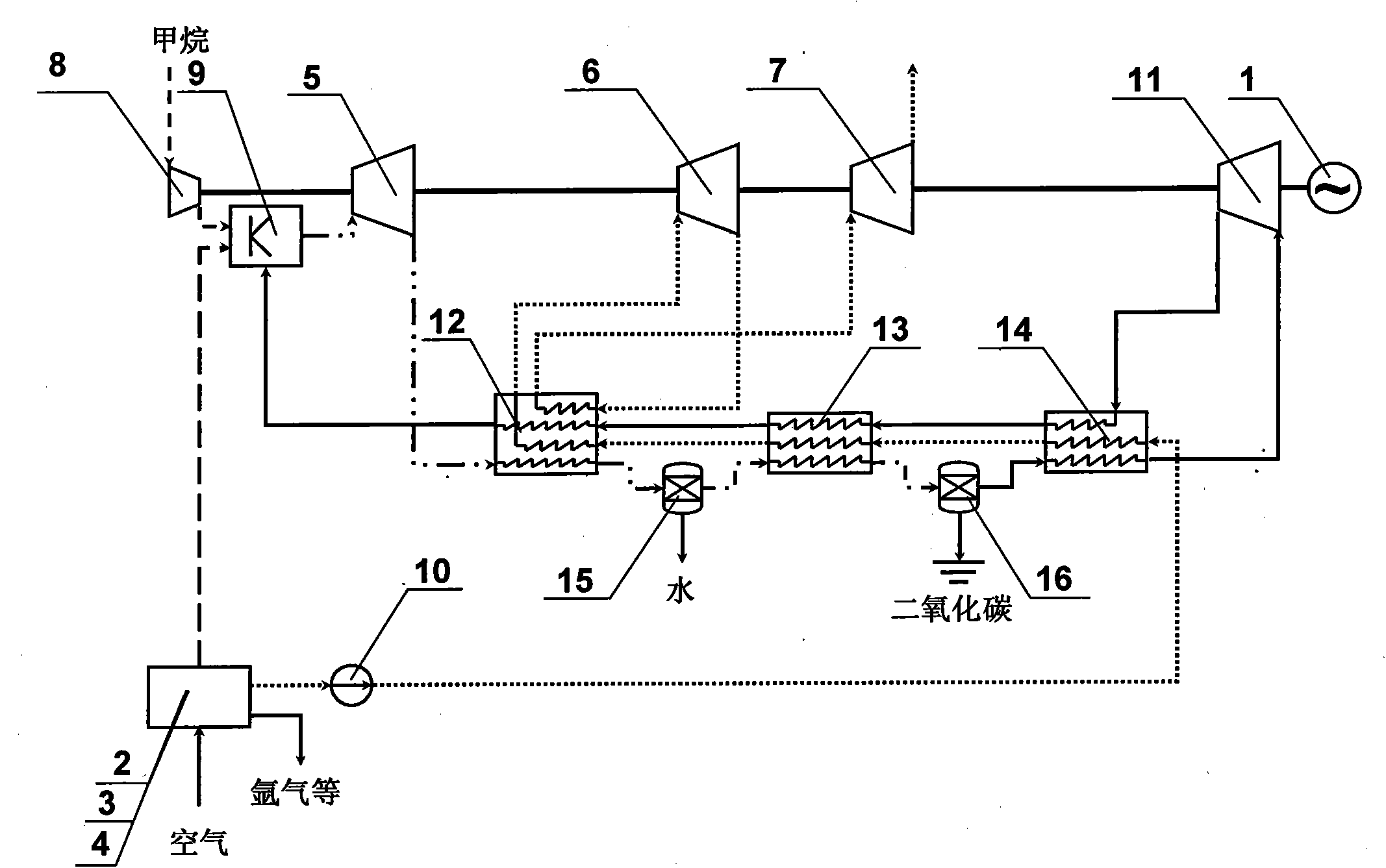
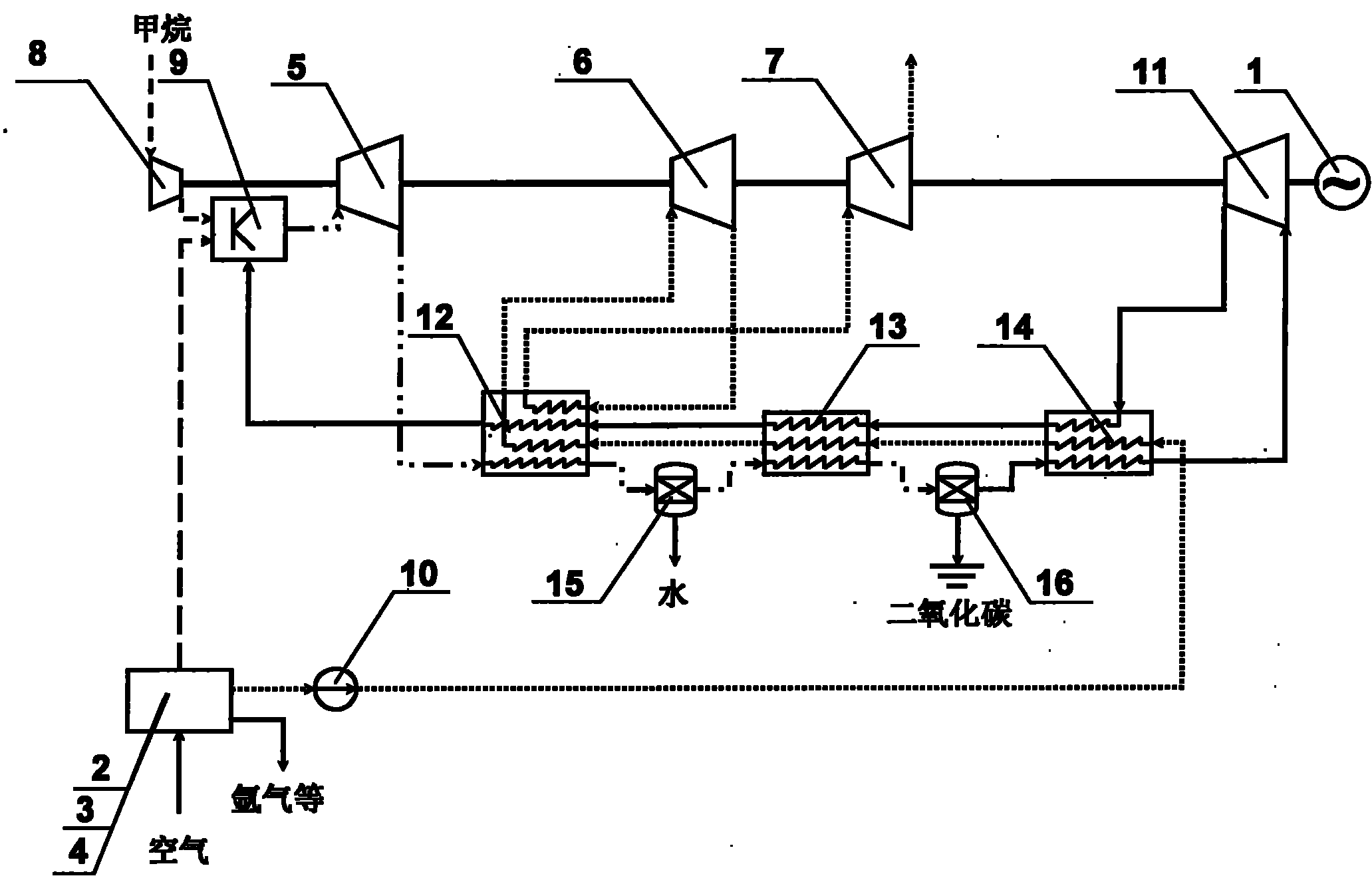
[0023] figure 1 -3 is a schematic diagram of an embodiment of the present invention, as can be seen from the figure, the high-peak load power generation device includes a generator 1, air separation and liquefaction equipment 2, a high-pressure gas storage tank 3, a low-temperature liquid storage tank 4, a gas turbine 5, a high-pressure Turbine 6, low-pressure turbine 7, three-stage multi-channel heat exchange device, compressor 8, combustion chamber 9, cryopump 10, helium compressor 11,

[0024] The combustion chamber 9 is connected to the methane compressor 8, the three-stage multi-channel heat exchange device, the high-pressure gas storage tank 3, and the gas tur...


PUM


Abstract

The invention discloses a peak load power generation device, which comprises a generator (1), space division and liquefaction equipment (2), a high-pressure air storage tank (3), a low-temperature liquid storage tank (4), a gas turbine (5), a high pressure turbine (6), a low pressure turbine (7), a three-level multi-channel heat exchange device, a methane compressor (8), a combustion chamber (9),a cryogenic pump (10) and a helium compressor (11). The device has a simple, reasonable and compact structure; and through the effective integration of a cryogenic energy storage technology and the conventional power generation system which uses natural gas as a fuel, a plurality of defects in the prior art are overcome, excessive loads in a low ebb period can be effectively recycled, and the quantity demand of the fuel in a peak period can be reduced, so that the device has the advantages that: high-grade cold energy and low-grade waste heat can be efficiently recycled and utilized, carbon dioxide generated by peak load equipment can be efficiently captured and stored, and environmental pollution is reduced.

Description

technical field [0001] The invention relates to the electric power industry, in particular to a peak load power generation device. Background technique [0002] Unlike the production and consumption chains of other commodities, there are few large-scale storage stages in the power industry, so the balance of supply and demand in the power industry has always been an important problem that plagues its development. Although large-scale pumped hydropower stations and compressed air energy storage technology can successfully adjust this supply-demand balance, their application is limited by the special geographical environment and construction period, so they are still far from meeting the requirements of the current power storage load. need. [0003] In the prior art, usually at the power grid production end dominated by thermal power or nuclear power, a peak power generation device with a certain load will be established to adjust the output of electric energy. In such a sys...

Claims


Application Information

Patent Timeline
Patent Type & Authority Applications(China)
IPC IPC(8): F02C3/20F01D15/10F02C7/141F02C7/18F01K25/00
Inventor 丁玉龙李永亮金翼陈海生谭春青
Owner 丁玉龙
Why Eureka
Try Eureka