Magnetic coupling microwave plasma igniter for automobile engine

A technology of microwave plasma and automobile engine, which is applied in the direction of engine ignition, plasma, engine components, etc., can solve the problems of large processing error, low repeatability, and inability to produce on a large scale, and achieve good tolerance performance and repeatability Good, consistent results

Inactive Publication Date: 2011-07-13
UNIV OF ELECTRONICS SCI & TECH OF CHINA
View PDF5 Cites 13 Cited by
  • Summary
  • Abstract
  • Description
  • Claims
  • Application Information

AI Technical Summary

Problems solved by technology

At this time, the traditional resonant cavity feeding coupling structure, such as ring coupling, requires manual assembly and debugging due to large processing errors and low repeatability, which cannot be mass-produced and cannot meet the design and application requirements.

Method used


Image

  • Magnetic coupling microwave plasma igniter for automobile engine
  • Magnetic coupling microwave plasma igniter for automobile engine
  • Magnetic coupling microwave plasma igniter for automobile engine

Examples


Embodiment 1

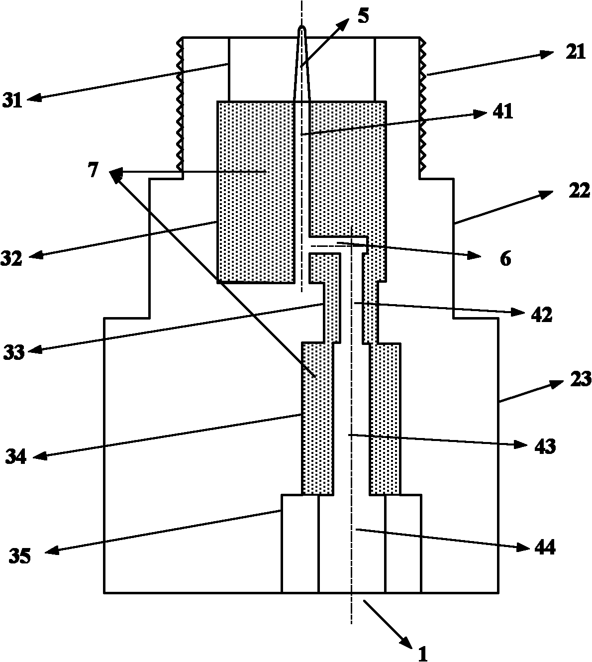
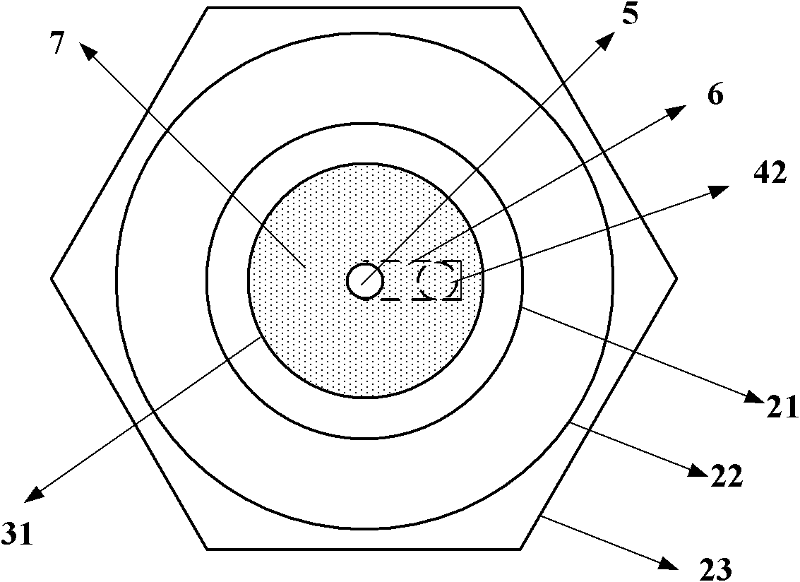
[0024] A magnetically coupled microwave plasma igniter for an automobile engine, comprising an inner conductor and an outer conductor; the outer conductor is composed of an outer contour of the outer conductor and an inner contour of the outer conductor closed; the outer contour of the outer conductor at least includes a The outer thread 21 connected by the cylinder and a hexagonal working surface 23 for easy disassembly and installation; the inner contour of the outer conductor is a cylindrical surface structure with different radii, including the inner contour of the outer conductor corresponding to the tip 5 of the inner conductor - 31 , the outer conductor inner contour two 32 corresponding to the inner conductor one 41, the outer conductor inner contour three 33 corresponding to the inner conductor two 42, the outer conductor inner contour four 34 corresponding to the inner conductor three 43, and the inner conductor three 43 corresponding to the outer conductor inner cont...

Embodiment 2

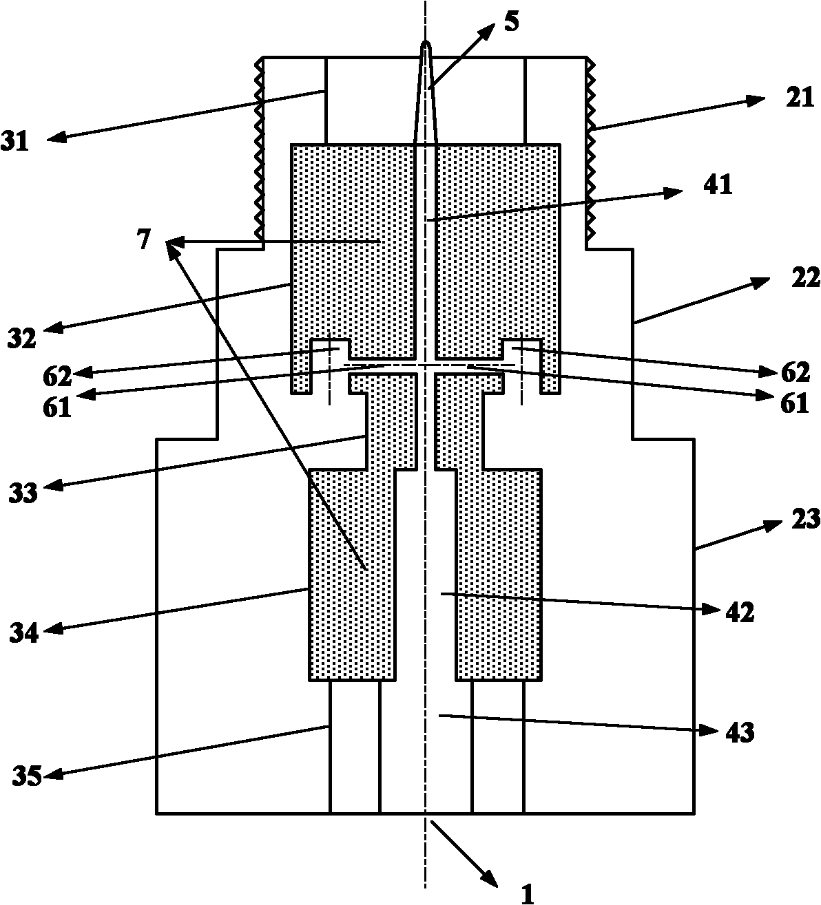
[0028] A magnetically coupled microwave plasma igniter for an automobile engine, comprising an inner conductor and an outer conductor; the outer conductor is composed of an outer contour of the outer conductor and an inner contour of the outer conductor closed; the outer contour of the outer conductor at least includes a The outer thread 21 connected by the cylinder and a hexagonal working surface 23 for easy disassembly and installation; the inner contour of the outer conductor is a cylindrical surface structure with different radii, including the inner contour of the outer conductor corresponding to the tip 5 of the inner conductor - 31 , the outer conductor inner contour two 32 and the outer conductor inner contour three 33 corresponding to the inner conductor one 41, the outer conductor inner contour four 34 corresponding to the inner conductor two 42, and the outer conductor inner contour corresponding to the inner conductor three 43 Five 35; the inner conductor includes i...


PUM


Abstract

The invention discloses a microwave plasma igniter for an automobile engine, which belongs to the technical field of microwave application. The invention provides seven microwave plasma igniters with different structures for the automobile engine igniter, and achieves extreme field intensity at an exciter end by using an electromagnetism principle that the voltage amplitude is maximum at the end of a quarter coaxial resonator. A top structure at the end of an inner conductor can further enhance the field intensity, thereby breaking down surrounding oil gas mixture and generating the plasma and igniting. Afterwards the rapid movement of electrons of the plasma in a combustor quickly realizes the volume combustion of the whole combustor and full combustion of the oil gas mixture. The engine igniter provided by the invention has a similar external profile to the conventional spark plug, and can directly replace the conventional spark plug ignition system on the basis of not changing an engine cylinder structure. The work center frequency is 2.45GHz. The engine igniter is designed integrally, and has the characteristics of high efficiency, low cost, easy mass production and the like.

Description

technical field [0001] The invention belongs to the technical field of microwave application, and relates to an ignition device of an automobile engine. Background technique [0002] In the 21st century, automobile pollution has increasingly become a global problem. With the increasing number of cars and their wider use, their negative effects on the world's environment are also increasing, especially in endangering the urban environment, causing respiratory diseases, causing excessive ozone content in the surface air, aggravating The urban heat island effect makes the urban environment deteriorate. With the increase in the number of motor vehicles, exhaust pollution has intensified. At the same time, with the continuous consumption of energy in the world and the continuous rise of oil prices, improving the combustion efficiency of the ignition system has become an effective method to relieve the pressure of energy shortage. Therefore, as the world's largest automobile pr...

Claims


Application Information

Patent Timeline
Patent Type & Authority Applications(China)
IPC IPC(8): F02P23/00H05H1/46
Inventor 樊勇程钰间郑伟
Owner UNIV OF ELECTRONICS SCI & TECH OF CHINA
Why Eureka
Try Eureka