Spiral-flow type blockage-free energy-efficient centrifugal fan

A centrifugal fan, non-clogging technology, applied in the direction of mechanical equipment, non-variable pumps, machines/engines, etc., can solve the problems of complex manufacturing process, non-optimal, loud noise, etc., achieve significant economic and social benefits, reduce energy Consumption, energy saving and emission reduction outstanding effect

Inactive Publication Date: 2011-07-20
SHANDONG UNIV
View PDF12 Cites 9 Cited by
  • Summary
  • Abstract
  • Description
  • Claims
  • Application Information

AI Technical Summary

Problems solved by technology

The disadvantages of the fan with this structure are that the mechanical loss, volume loss and flow loss are large, and it has the disadvantages of low efficiency, high energy consumption, small air volume, high noise, short life, etc. The impeller structure has many consumables, high cost, and manufacturing Complicated process and other deficiencies
[0004] Chinese Invention Patent Application Publication CN200810016349.9 provides a high-efficiency multifunctional centrifugal fan, and Chinese Invention Patent Examination and Authorization Specification CN200810017064.7 provides a structural high-efficiency energy-saving non-stick oil range hood, the commonality of the two patents The characteristic is that the impeller is composed of at least one group of arc-shaped flow channel blades with one side closed and axially enlarged. The manufacturing process of the arc-shaped flow channel blades with this structure is relatively complicated and the production efficiency is low. Experiments show that its performance is not The best; the inside of the casing is a circular double-chamber or multi-chamber with an air inlet and an air outlet. When the gas enters the air inlet, the casing of this structure diffuses sharply, which will cause a violent collision to the casing, and make a lot of noise
[0005] Chinese Invention Patent Application Publication CN200910013929.7 provides a new swirling high-efficiency energy-saving and environmental protection range hood. The side and the impeller disk are in a radial parabolic arc vertical conjoined structure. Experiments have proved that the oil fume suction and exhaust effect of the impeller with this structure is not optimal

Method used


Image

  • Spiral-flow type blockage-free energy-efficient centrifugal fan
  • Spiral-flow type blockage-free energy-efficient centrifugal fan
  • Spiral-flow type blockage-free energy-efficient centrifugal fan

Examples


Embodiment Construction

[0022] The present invention will be further described below in conjunction with the accompanying drawings and embodiments.

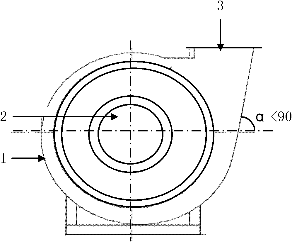
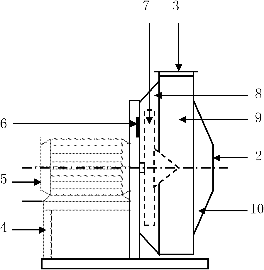
[0023] A swirling non-blocking energy-saving centrifugal fan, which includes a casing 1, an air inlet 2, an air outlet 3, a frame 4, a motor 5, an adjustable wheel guard hole 6, an impeller 7, a frustum-shaped induction chamber 8, Circular or volute-shaped swirl chamber 9, umbrella-shaped diffuser chamber 10, such as figure 1 , figure 2 shown.

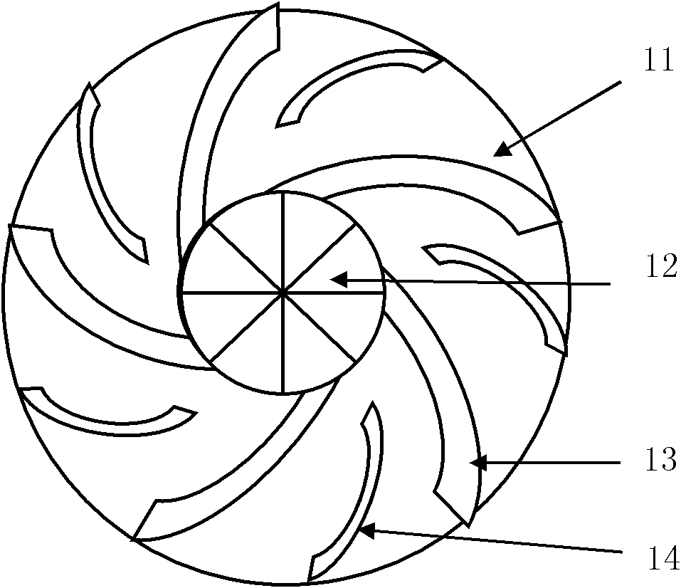
[0024] Install the motor 5 and the casing 1 on the frame 4, the casing 1 is provided with an air inlet 2 and an air outlet 3, and the casing 1 is composed of a frustum-shaped induction chamber 8, a circular or volute-shaped swirl chamber 9 and an umbrella-shaped diffuser chamber 10, the impeller 7 is installed in the frustum-shaped induction chamber 8, and is directly connected with the motor 5; the impeller 7 is a blade-type disc impeller and a bevel-toothed impeller with one side open in the axial direction...


PUM


Abstract

The invention relates to a spiral-flow type blockage-free energy-efficient centrifugal fan which comprises a rack, an enclosure, an impeller and a motor, wherein the enclosure is composed of a frustum-shaped flow inducing chamber, a round or volute-shaped spiral-flow chamber and an umbrella-type flow expanding chamber, wherein the impeller is of a dual-wheel structure which is composed of a blade-type circular disk impeller opened axially and unilaterally and a conical tooth-form impeller; the blade-type circular disk impeller is provided with two groups of long blades and short blades, and the long blades and the short blades are same in number and are distributed alternatively and uniformly, or the impeller disk provided with two groups of high blades and low blades, and the high blades and the low blades are same in number and are distributed alternatively and uniformly; the long blades and the short blades or the high blades and the low blades are vertically linked with the impeller disk in an circular arc shape which expand axially and radially; and the frustum-shaped impeller is a conical body the tooth surface of which is of an involute profile. The working principle of the fan of the structure is that gas (or a material) is delivered by a gas spiral flow field in a 'gas driven by gas' mode, but not delivered by the rotary impeller or blades; the fan has the characteristics of high efficiency, less energy consumption, low noise, no blockage, long service life, less material consumption, multiple functions and the like, and is easy to manufacture, and the comprehensive economic and technical norms of the fan reach the domestic and international leading level; and the fan has various functions such as air ventilation, air delivery, air induction, smoke exhaustion, dust absorption, material suction and exhaustion, and the like, and has the advantages of obvious energy conservation and emission reduction effects and remarkable economic and social benefits.

Description

technical field [0001] The invention is a swirl type non-clogging energy-saving centrifugal fan, which belongs to the field of energy-saving equipment manufacturing and automation. Background technique [0002] As we all know, fans are mechanical products with wide application, large consumption and high energy consumption. From a discipline point of view, fan is the application and development of fluid mechanics. From the perspective of energy, the fan is a type of fluid machinery that can convert the mechanical energy of the prime mover into the pressure potential energy and kinetic energy of the conveyed fluid. Fans are widely used in various sectors of the national economy, such as the ventilation of tunnels in the mining industry; the blasting of various smelting furnaces and the transportation of gases in the metallurgical industry; Emission and transportation; in general industry, air conditioning of workshops and workshops, ventilation of atomic protection equipmen...

Claims


Application Information

Patent Timeline
Patent Type & Authority Applications(China)
IPC IPC(8): F04D25/08F04D29/28
Inventor 朱瑞富朱先俊王建华
Owner SHANDONG UNIV
Why Eureka
Try Eureka