Multifunctional photocatalytic reaction device

A photocatalytic reaction and multi-functional technology, applied in the field of chemical engineering, can solve the problems of high recovery cost, unfavorable post-processing, complex processing, etc., and achieve the effects of convenient product detection, improved light utilization rate, and stable performance.

Inactive Publication Date: 2014-02-26
NORTHWEST UNIV
View PDF1 Cites 3 Cited by
  • Summary
  • Abstract
  • Description
  • Claims
  • Application Information

AI Technical Summary

Problems solved by technology

For example, the current photocatalytic reduction CO2 reaction devices are in various forms, either fixed or suspended. The fixed type can solve the problem of photocatalyst recovery, but the specific surface area of ​​the catalyst is greatly reduced. , the utilization rate of light is not high; the suspended photoreactor can greatly improve the photocatalytic efficiency, but the recovery of photocatalyst is difficult and the recovery cost is high; and the existing photocatalytic reactor is not conducive to the study of reaction kinetics, and the purpose is single and flexible small
For example, the three-phase ultrasonic photocatalytic reaction device disclosed in the Chinese patent application (application number: 200710062204.8) and its method for reducing CO2 belong to the suspension reaction system, which is not conducive to post-reaction treatment; the design by Nguyen et al. Optical-Fiber Catalytic Reactor, (Nguyen TV, Wu. J C S. Photoreduction of CO2 to Fuels under Sunlight Using Optical-Fiber Reactor. Sol Energy Mater Sol Cells. 2008, 92(8): 864- 872) TiO2 is loaded on the optical fiber, which is a fixed reaction system. Its processing is complicated, the cost is high, and it is difficult to popularize. It is not suitable for the screening of photocatalysts.

Method used


Image

  • Multifunctional photocatalytic reaction device
  • Multifunctional photocatalytic reaction device
  • Multifunctional photocatalytic reaction device

Examples


Embodiment Construction

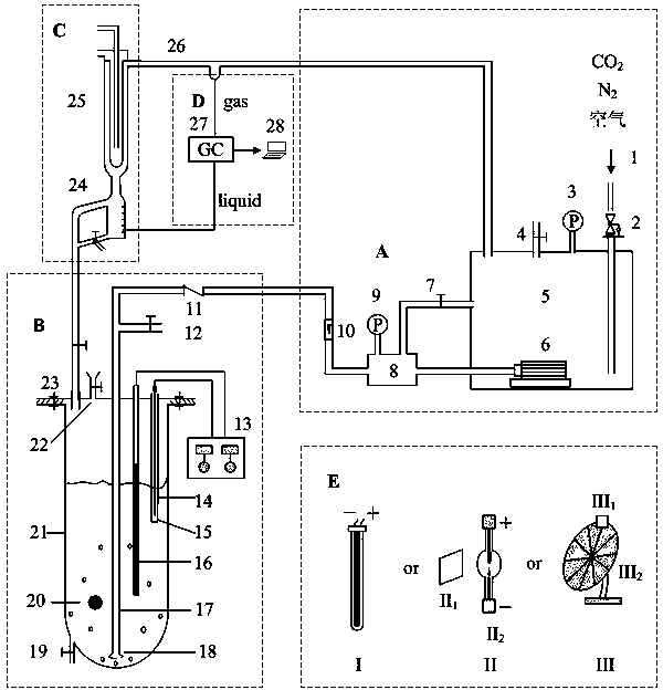
[0030] see figure 1 , The multifunctional photocatalytic reaction device of the present invention is composed of a gas circulation system, a photoreaction system, a separation system, a detection system and a light source system. The entire device is connected by pipelines, and the airtightness of the device is particularly critical. with CO 2 in H 2 Using photocatalytic reduction in O as an example, each system will be described.

[0031] 1. Gas circulation system (A)

[0032] gas circulation system (A) It includes a sealed box 5 on which a pressure reducing valve 2, a first pressure gauge 3, a vent valve 4 and a bypass regulating valve 7 are installed. The bypass regulating valve 7 is connected to a gas buffer tank 8 through a pipeline, and the gas buffer The second pressure gauge 9 is installed on the tank 8, the gas buffer tank 8 is connected with the gas compressor 6, and the gas buffer tank 8 is also communicated with the check valve 11 of the photoreaction system ...


PUM


Abstract

The invention discloses a multifunctional photocatalytic reaction device, which consists of a gas circulation system, a photoreaction system, a separation system, a detection system and a light source system. The light source can be ultraviolet light, visible light and sunlight and is arranged outside a quartz reactor, light penetrates through the quartz reactor to excite a photocatalyst in order to initiate photocatalytic reaction, the photocatalyst can be a thin film which is immobilized, together with a carrier, inside the reactor, or be particles suspended in reaction liquid. The reactor is suitable for liquid-solid, gas-solid and gas-liquid-solid phase photocatalytic reaction, favoring the research on photocatalytic reaction dynamics. The multifunctional photocatalytic reaction device of the invention is suitable not only for photocatalytic reduction CO2 reaction, but also for the fields such as photocatalytic degradation of organic pollutants, hydrogen production by water photolysis, photochemical synthesis and the like, besides, both intermittent operation and continuous operation can be implemented, and inert gas protection can be performed in the reaction process.

Description

technical field [0001] The invention belongs to the technical field of chemical engineering, and is a multifunctional photocatalytic reaction device, which is suitable for photocatalytic reduction of CO 2 , photolysis of water to produce hydrogen, photocatalytic degradation of organic pollutants, photochemical synthesis and other fields, it can be operated continuously or intermittently, and has the function of inert gas protection. Background technique [0002] In 1972, Fujishima and Honda reported on Nature that TiO in light radiation 2 In a battery composed of semiconductor electrodes and metal electrodes, the oxidation-reduction reaction of water can continue to occur, generating H 2 , indicating that light energy can be converted into chemical energy through semiconductor electrodes. Since then, the photocatalytic performance of semiconductor materials has attracted people's attention, and the application field of photocatalytic technology has been continuously expande...

Claims


Application Information

Patent Timeline
Patent Type & Authority Patents(China)
IPC IPC(8): B01J19/12B01J8/00
Inventor 樊君刘恩周胡晓云谭春雷何奇孙涛温凯汤春妮
Owner NORTHWEST UNIV
Why Eureka
Try Eureka