Flue gas flow velocity measuring device and method

A flue gas flow velocity and measuring instrument technology, which is applied in fluid velocity measurement, average velocity measurement, velocity/acceleration/shock measurement, etc., can solve the problems of unable to measure light flicker signal, no future, smoke and dust concentration cannot be measured, etc., to achieve measurement The effect of high precision and increased reliability

Inactive Publication Date: 2011-08-17
ANHUI INST OF OPTICS & FINE MECHANICS - CHINESE ACAD OF SCI
View PDF5 Cites 24 Cited by
  • Summary
  • Abstract
  • Description
  • Claims
  • Application Information

AI Technical Summary

Problems solved by technology

Because the distance between the two receiving lenses is too close, the light flicker caused by the fluctuation of the flue gas concentration with a lower frequency and a larger correlation scale (equivalent to the diameter of the flue) cannot be used
[0004] On the measurement method of light flicker based on the random distribution of particle extinction characteristics, domestic Tsinghua University, Zhejiang University, University of Shanghai for Science and Technology and many other units have carried out similar research, but their work still has a large gap in practical application. There are three main reasons for the defect: 1) When there are too many particles passing through the beam, the light flicker signal is very weak, that is, it cannot be measured

Method used


Image

  • Flue gas flow velocity measuring device and method
  • Flue gas flow velocity measuring device and method
  • Flue gas flow velocity measuring device and method

Examples


Embodiment Construction

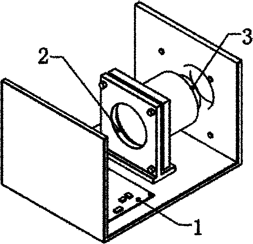
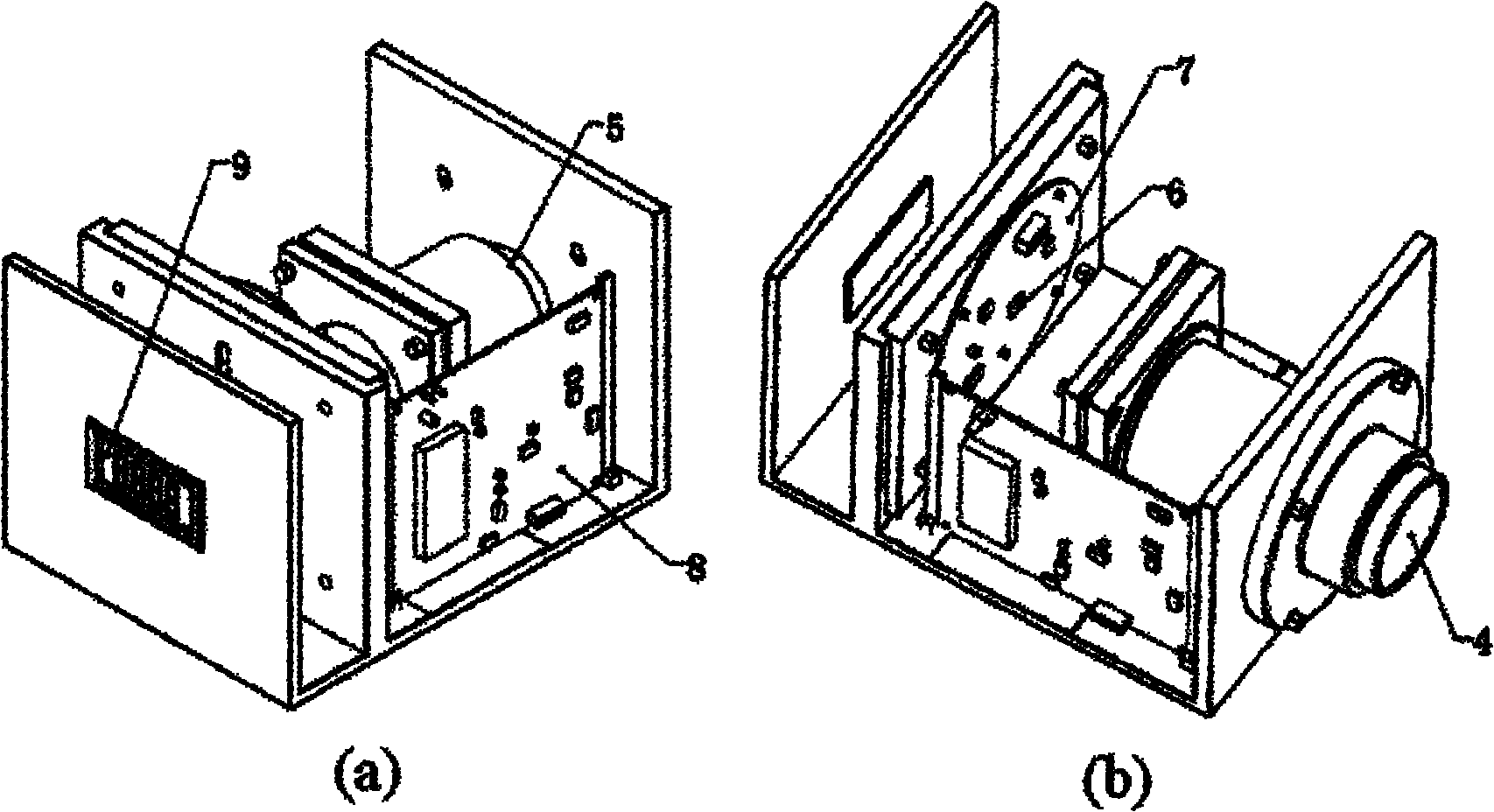
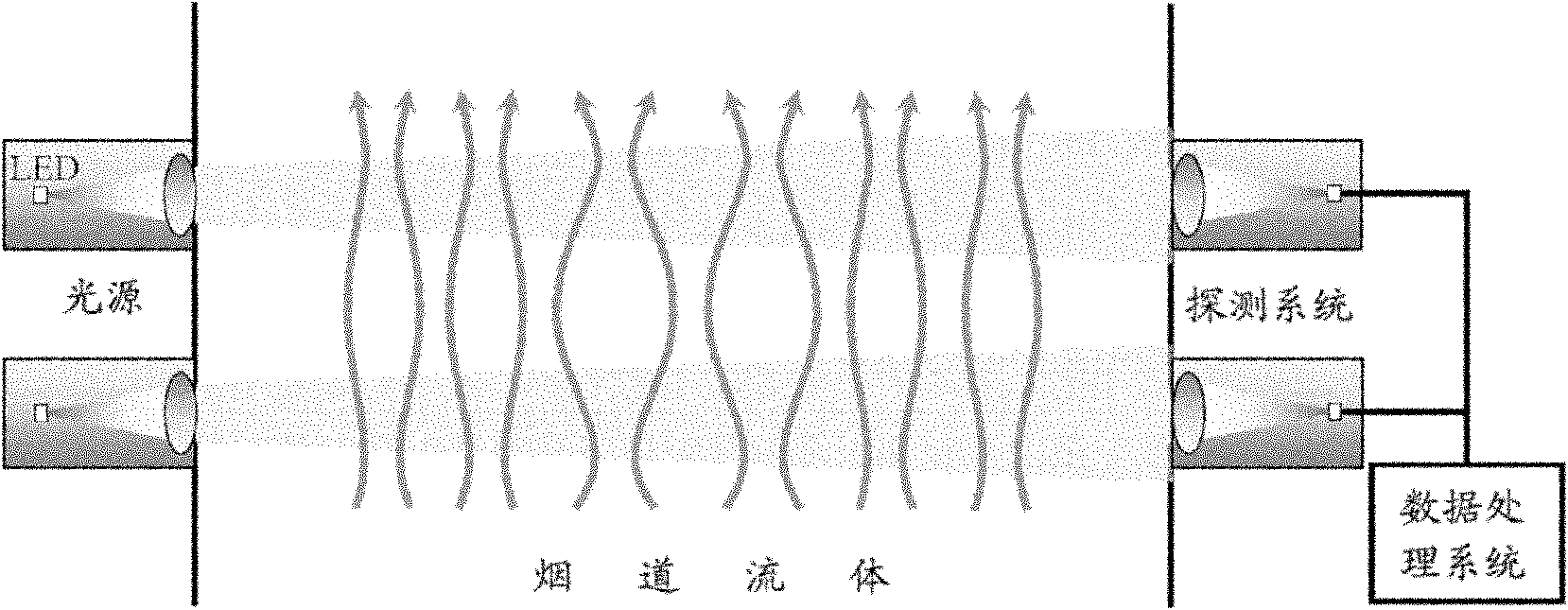
[0033] see figure 1 , 2 , 3, a flue gas flow rate measuring instrument, including two groups of light emitting system and light receiving system located on both sides of the flue, wherein the light emitting system includes an LED light source 2 and a collimating lens located on the outgoing light path of the LED light source 2 3. The light receiving system includes a focusing lens 5 and a photodetector 6 located on the transmission light path of the focusing lens 5. The light beam emitted by the LED light source 2 is collimated by the collimator lens 3 into a parallel beam and then passes through the flue. 5 to receive and send to the photodetector; the photodetector is externally connected to the digital display 9 through the data processing system.

[0034] The LED light source 2 is driven by the constant current source 1; the front end of the focusing lens 5 is equipped with a dust cover 4.

[0035] A method for measuring flue gas flow velocity, specifically comprising th...


PUM


Abstract

The invention discloses a flue gas flow velocity measuring device and method. The flue gas flow velocity measuring device comprises two groups of light emitting systems and light receiving systems which are respectively arranged at two sides of a flue, wherein each light emitting system comprises an LED light source and a collimating lens located on an exiting light path of the LED light source; each light receiving system comprises a focusing lens and a photoelectric detector located on a transmittance light path of the focusing lens; light beams emitted by the LED light source are collimated to parallel light beams through the collimating lens and then to pass through the flue, then the parallel light beams are received by the focusing lens and sent to the photoelectric detector; and a digital display is connected outside the photoelectric detector through a data processing system. In the invention, a high frequency flash signal caused by temperature fluctuation can be measured, anda low frequency flash signal caused by smoke dust concentration fluctuation can also be processed at the same time; a light flash signal can be obtained under the condition that the turbulent flow ofa flue refractive index is very weak (light velocity and flow meters can not be adopted); and the flue gas flow velocity measuring device has the characteristics of high measurement precision, non-interference, convenience for installation, broader application range and the like.

Description

technical field [0001] The invention relates to the technical field of pipeline flow velocity measurement, in particular to a smoke flow velocity measuring instrument and a measuring method. Background technique [0002] Particulate matter has very serious harm to human health, industrial production, ecological environment and other fields. In order to control and control pollution, it is necessary to implement continuous online monitoring of pollutant emissions from industrial enterprises, and to accurately measure the concentration of particulate matter and the total amount of emissions. Among the flue gas emission monitoring instruments, there are many instruments for measuring flue gas flow velocity and particle concentration, among which the light scintillation method is a unique and superior monitoring method, which uses non-intrusive light scintillation technology to measure simultaneously Smoke flow rate and particulate matter concentration. Because of its non-inte...

Claims


Application Information

Patent Timeline
IPC IPC(8): G01N21/59G01P5/26G01P11/00G01N15/06
Inventor 董凤忠杨阳倪志波庞涛张志荣吴边曾宗泳
Owner ANHUI INST OF OPTICS & FINE MECHANICS - CHINESE ACAD OF SCI
Why Eureka
Try Eureka