
Airfoil type axial-flow stirrer

An axial flow, agitator technology, applied in mixers with rotary stirring devices, chemical/physical/physical-chemical stationary reactors, chemical instruments and methods, etc., can solve the problem of increasing agitator vibration, large fluid resistance, Less specifications, etc., to achieve the effect of strengthening axial circulation and flow, optimizing hydraulic performance, and improving flow performance

Inactive Publication Date: 2011-09-14
ZHEJIANG UNIV
View PDF3 Cites 9 Cited by
  • Summary
  • Abstract
  • Description
  • Claims
  • Application Information

AI Technical Summary

Problems solved by technology

Commonly used axial flow agitators are pusher agitators and 45° inclined blade turbines. The pusher agitators have the advantages of large axial displacement and high efficiency, but because they are manufactured by mold casting, the cost is high and the specifications are small. Cannot be used in mixing equipment
The 45° inclined blade turbine is simple in design, low in manufacturing cost, and easy to be enlarged. However, since the pitch angle of the blade is constant, the pitch varies from the root of the blade to the tip of the blade at different radii, resulting in uneven axial velocity distribution of the fluid. And the tangential velocity is large, the fluid resistance is large, the power consumption is high, and the mixing effect is not ideal
If an ordinary axial-flow agitator is used, the impact of the fluid on the back of the blade surface of the agitator is greater, which increases the vibration of the agitator, and the blades of the agitator will affect the transmission and escape of gas

Method used


Image

  • Airfoil type axial-flow stirrer
  • Airfoil type axial-flow stirrer
  • Airfoil type axial-flow stirrer

Examples


Embodiment 1

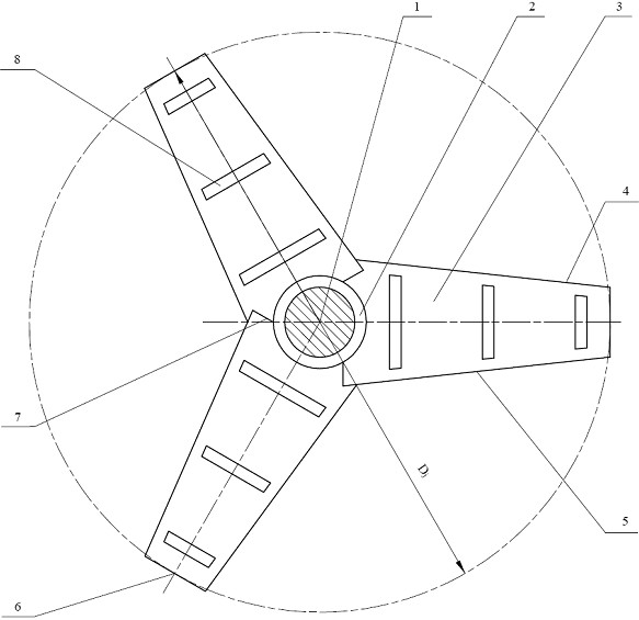
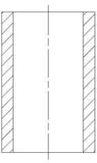
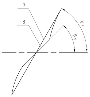
[0020] A nitration reaction kettle with an effective volume of 50 L, the inner diameter of the reaction kettle is 500 mm, and the height-to-diameter ratio of the kettle body is 1. The airfoil axial flow agitator designed by the present invention is used for the nitration reaction. The structure of the agitator is shown in the attached figure 1 to attach Figure 5 .

[0021] The diameter of the airfoil impeller D j The ratio to the inner diameter of the reactor is 0.5, and the pitch angle β at the end of the blade b is 45°, the pitch angle β at the blade root a is 60°, the pitch angle β of any section at different radii from the blade tip to the blade root i Designed according to equal pitch structure, pitch angle β i It increases continuously from the tip of the blade to the root of the blade. The ratio of the arc height h to the chord length a of an arc of any cross section is 0.06. The blade width of the paddle blade gradually increases from the blade end to the blade ...

Embodiment 2

[0024] A nitration reaction kettle with an effective volume of 200 L and an inner diameter of 700 mm uses the airfoil axial flow agitator designed by the present invention for nitration reaction. For the structure of the agitator, see the attached figure 1 to attach Figure 5 .

[0025] The diameter of the airfoil impeller D j The ratio to the inner diameter of the reactor is 0.4, D j =280 mm. The pitch angle β at the tip of the blade b is 45°, the pitch angle β at the blade root a is 60°, the pitch angle β of any section at different radii from the blade tip to the blade root i Designed according to equal pitch structure, pitch angle β i It increases continuously from the tip of the blade to the root of the blade. The ratio of the arc height h to the chord length a of an arc of any cross section is 0.06. The blade width of the paddle blade gradually increases from the blade end to the blade root, and the width B of the blade end b is 35 mm, the width B of the blade r...

Embodiment 3

[0028] The nitrification reaction kettle with an effective volume of 700 L, the inner diameter of the reaction kettle is 1000 mm, and the airfoil axial flow agitator designed by the present invention is used for the nitrification reaction. The structure of the agitator is shown in the appendix. figure 1 to the attached Figure 5 .

[0029] The diameter D of the airfoil stirring paddle j The ratio to the inner diameter of the reactor is 0.45, D j =450mm. The pitch angle β of the blade end b is 45°, the pitch angle β at the root of the blade a is 60°, the pitch angle β of any section at different radii from the end of the blade to the root of the blade i Designed according to the equal pitch structure, the pitch angle β i It increases continuously from the tip of the blade to the root of the blade. The ratio of the arc height h to the chord length a of any cross-sectional arc is 0.06. The blade width of the paddle blade gradually increases from the blade end to the blade...


PUM


Abstract

The invention discloses an airfoil type axial-flow stirrer, which comprises a stirring shaft, a hub and a propeller blade, wherein the hub is mounted on the stirring shaft; the propeller blade can be mounted on the hub removably or irremovably; the propeller blade of the stirrer has a smooth special distortion face, the cross section at any radius position is in an airfoil shape, the angle of pitch and blade width increase continuously from the end part to root part of the blade, and the design is based on a uniform pitch structure; and a plurality of isosceles trapezoid-shaped channels, which are vertical to the central line of the blade, are formed on the blade and are symmetrically distributed on the blade. The airfoil type axial-flow stirrer has the advantages that: the impact force applied by a fluid on the back of the stirring propeller blade face is reduced; the vibration of the stirrer is reduced; the axial circulation and flowing are reinforced; the flowing property of fluid in the reaction kettle is improved obviously; the liquid and solid phases are well separated; the stirring of the materials in the kettle is uniformly; and gases formed by reaction can be conveyed and allowed to escape smoothly to guarantee a normal reaction. In addition, the stirring power of the airfoil type stirrer is smaller than common airfoil propeller, so the energy consumption is low.

Description

technical field [0001] The invention relates to an agitator, in particular to an airfoil axial flow agitator. Background technique [0002] Stirring and mixing equipment is widely used in various industries such as chemical industry, light industry, and pharmaceutical industry. As an important operating unit, its main function is to transfer energy to liquid and other materials through the agitator, allowing it to move radially or axially, so that two or more liquid or solid materials or between the two can be fully mixed. Various processes such as mixing, stirring, dissolving, dispersing, and reacting. [0003] At present, the paddle forms commonly used in agitators are: axial flow stirring paddle, long blade propeller, straight blade turbine paddle, plate frame paddle, three-blade back curved paddle, MIG type paddle, anchor paddle, screw type paddle, There are several types such as single-screw ribbon impeller, double-screw ribbon agitator and helix-screw ribbon impeller...

Claims


Application Information

Patent Timeline
IPC IPC(8): B01J19/18B01F7/06B01F7/22B01F27/71B01F27/91
Inventor 车圆圆何潮洪周俊超吴可君
Owner ZHEJIANG UNIV
Learn More