Super-gravity device used for electrochemical deposition in ionic liquid

An ionic liquid and electrochemical technology, applied in the field of electrochemical deposition, can solve the problems of easy occurrence of impurities, unstable operation of supergravity devices, and no cooling system for the centrifugal shaft, and achieve the effect of a strict speed measurement system and a speed control system.

Inactive Publication Date: 2011-09-14
BEIJING UNIV OF CHEM TECH
View PDF3 Cites 8 Cited by
  • Summary
  • Abstract
  • Description
  • Claims
  • Application Information

AI Technical Summary

Problems solved by technology

However, this device has many disadvantages: the stainless steel electrolytic cell is easily corroded, and impurities are easy to appear during the deposition process; there is no protection of inert gas during the electrodeposition process of the electrolytic cell, which easily causes the i...

Method used


Image

  • Super-gravity device used for electrochemical deposition in ionic liquid
  • Super-gravity device used for electrochemical deposition in ionic liquid
  • Super-gravity device used for electrochemical deposition in ionic liquid

Examples


Embodiment 1

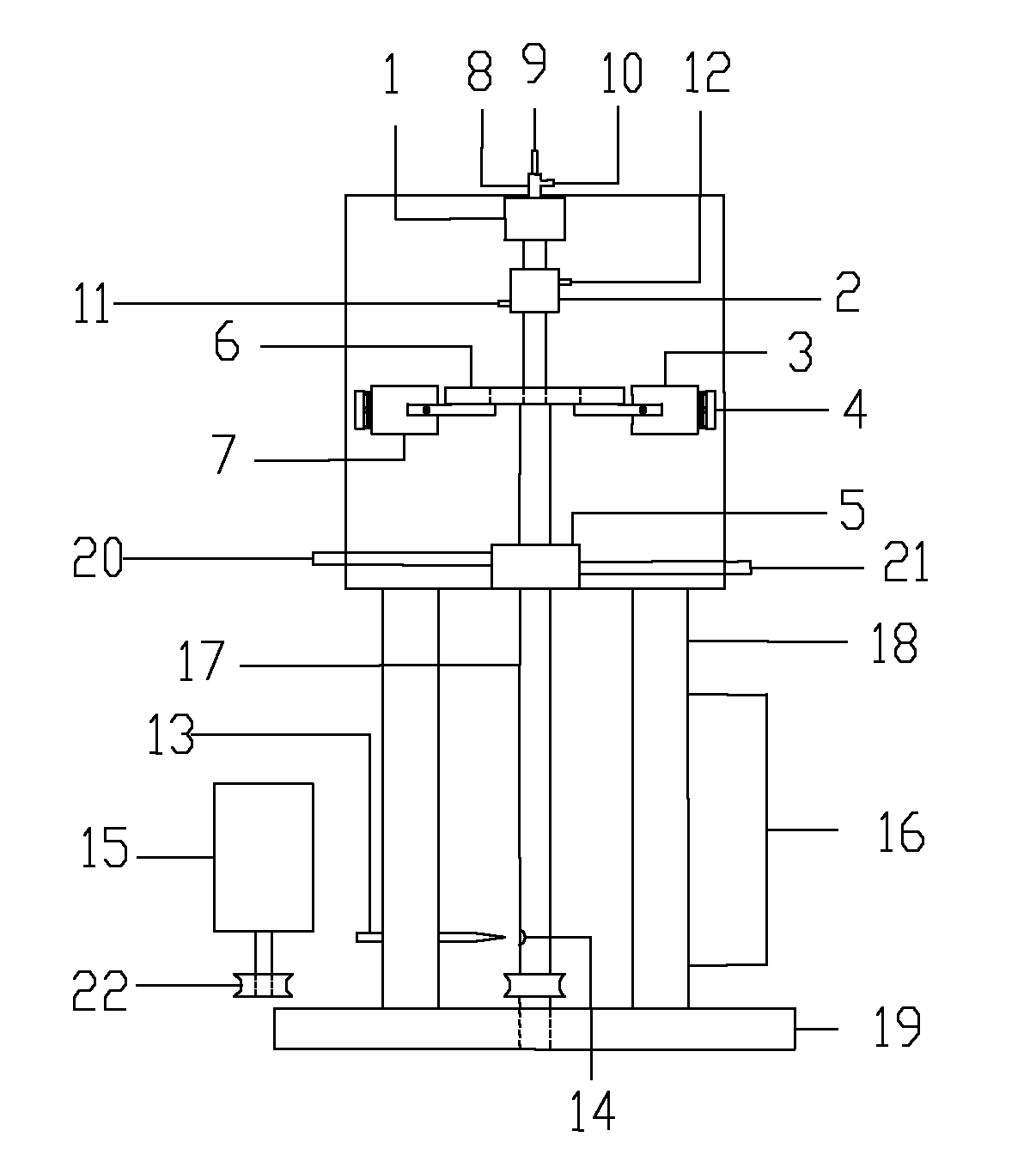
[0037] Utilize the hypergravity device described in the present invention, in AlCl 3 The experiment of electrodepositing aluminum was carried out in the ionic liquid with the molar ratio of TMPAC and TMPAC being 2:1. First, under the protection of high-purity argon, at a temperature of 60°C, accurately weighed anhydrous AlCl 3 Add it to TMPAC several times in small amounts, and stir at 80°C for 2-3 hours after the addition to obtain an ionic liquid. Then, the ionic liquid is used as the electrolyte, the copper sheet is used as the cathode, and the aluminum-based composite material is used as the anode. The two electrodes are placed parallel to the direction of the centrifugal force, the distance between the cathode and the anode is fixed at 1.5 cm, and the electrodeposition time is fixed at 2 hours. Effects of density, temperature and rotational speed on electrodeposition experiments.

[0038] Before the experiment started, the pretreatment process of the electrode sheet was...

example 2

[0044] Utilize the hypergravity device described in the present invention, in AlCl 3 The experiment of electrodepositing aluminum was carried out in the ionic liquid with the molar ratio of BMIC and BMIC being 2:1. The ionic liquid was first synthesized by the experimental method in Example 1. In the experiment, a copper sheet was used as the working electrode, and an aluminum-based composite material was used as the counter electrode. The treatment method of the electrode sheet and the deposited material obtained after the electrodeposition were all adopted the method in Example 1. The electrodes were weighed with an electronic balance before and after deposition.

[0045] At a temperature of 80°C, an electrodeposition time of 2h, and a current density of 11mA / cm 2 , AlCl 3 The electrodeposition experimental conditions and experimental conclusions carried out in the ionic liquid with a molar ratio of BMIC of 2:1 are as follows:

[0046]


PUM


Abstract

The invention discloses a super-gravity device used for electrochemical deposition in ironic liquid, and belongs to the field of the electrochemical deposition under a special condition. The super-gravity device comprises an electrolytic tank, a balance weight system, a shaft cooling system, a shielding gas transmission system, a speed measurement system, a rotating speed and temperature control display system and a conducting slip ring system. In the reaction process, a motor drives a shaft to rotate to supply required centrifugal force; the centrifugal force is measured by a super-gravity coefficient; the super-gravity coefficient is calculated by the speed measurement system; the temperature in the electrolytic tank is controlled by the temperature control system; the dynamic balance of the electrolytic tank in a centrifugal field is realized through the balance weight system; an inert gas atmosphere required by the reaction is realized through the shielding gas transmission system; the shaft cooling of the super-gravity device is realized through the shaft cooling system; and the current required in the electro-deposition process is supplied by the conducting slip ring system.

Description

technical field [0001] The invention belongs to the field of electrochemical deposition under special conditions, and in particular relates to a high-gravity device used for electrochemical deposition in ionic liquid. Background technique [0002] Ionic liquids are substances composed of specific cations and anions that are liquid at room temperature or near room temperature, also known as room temperature molten salts. Ionic liquids combine the advantages of high-temperature molten salts, organic solvents, and aqueous solutions: 1. Metals and alloys that can only be obtained in high-temperature molten salts can be obtained at room temperature, and they are not as corrosive as high-temperature molten salts; 2. Ionic liquids are almost There is no vapor pressure, less volatile substances are released during the electrodeposition process, and less environmental pollution; 3. In ionic liquids, not only metals that can be obtained in aqueous solutions such as Cu, Ag, Pt, etc. ca...

Claims


Application Information

Patent Timeline
IPC IPC(8): C25C7/06
Inventor 徐联宾崔节振陈建峰尹小梅向前
Owner BEIJING UNIV OF CHEM TECH
Why Eureka
Try Eureka