Metal deposition method and laser metal deposition apparatus

A laser surfacing and cooling device technology, which is applied in laser welding equipment, chemical instruments and methods, welding/welding/cutting items, etc., can solve the problems of dendrite amplitude increase and temperature gradient change

Inactive Publication Date: 2011-10-12
HITACHI LTD
View PDF11 Cites 2 Cited by
  • Summary
  • Abstract
  • Description
  • Claims
  • Application Information

AI Technical Summary

Problems solved by technology

[0005] In addition, in the repair method of the above-mentioned prior art document, the following characteristic change becomes a problem. In the case where the lower layer and the upper layer of the stack are constructed under the same conditions, the temperature gradient in the upper layer is different from that in the case of construction in the lower layer. Compared with large changes, the amplitude of dendrites becomes larger, etc.

Method used


Image

  • Metal deposition method and laser metal deposition apparatus
  • Metal deposition method and laser metal deposition apparatus
  • Metal deposition method and laser metal deposition apparatus

Examples


Embodiment 1

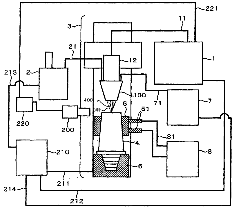
[0030] figure 1 The laser deposition welding apparatus of Example 1 is shown. 1 denotes a laser oscillator, 11 denotes an optical fiber, 12 denotes a laser welding head, 2 denotes a powder supply device, 21 denotes a powder supply tube, 3 denotes a three-dimensional NC processing device, 4 denotes a single crystal movable blade, 5 denotes a cooling fixture, 51 denotes a refrigeration Agent introduction and discharge port, 6 indicates movable blade fixing fixture, 7 indicates gas supply source, 71 indicates gas supply pipe, 8 indicates refrigerant supply, circulation and heat exchange device, 81 indicates refrigerant supply pipe, 100 indicates powder and protective gas The supply nozzle, 200 indicates the temperature measuring device of the construction department, 210 indicates the NC control panel, 211 indicates the signal line connected to the three-dimensional NC processing machine, 212 indicates the signal line connected to the laser oscillator, and 213 indicates the signa...

Embodiment 2

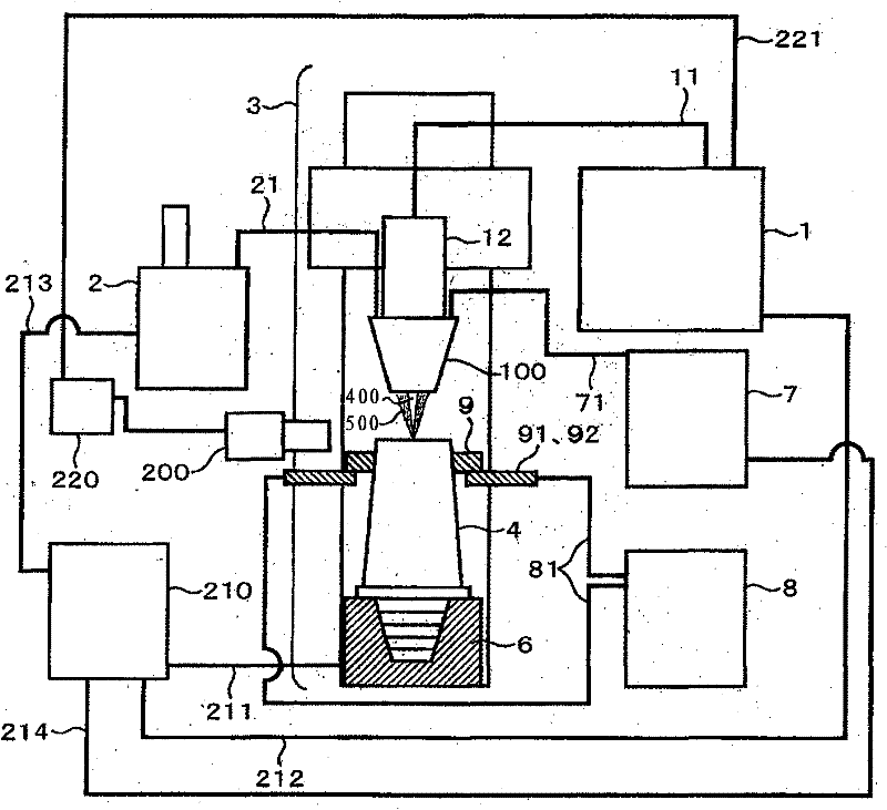
[0037] image 3 The laser deposition welding apparatus of Example 2 is shown. Its structure is a structure in which the refrigerant clamp 5 is changed to the direct refrigerant clamp 9 in the structure of the first embodiment.

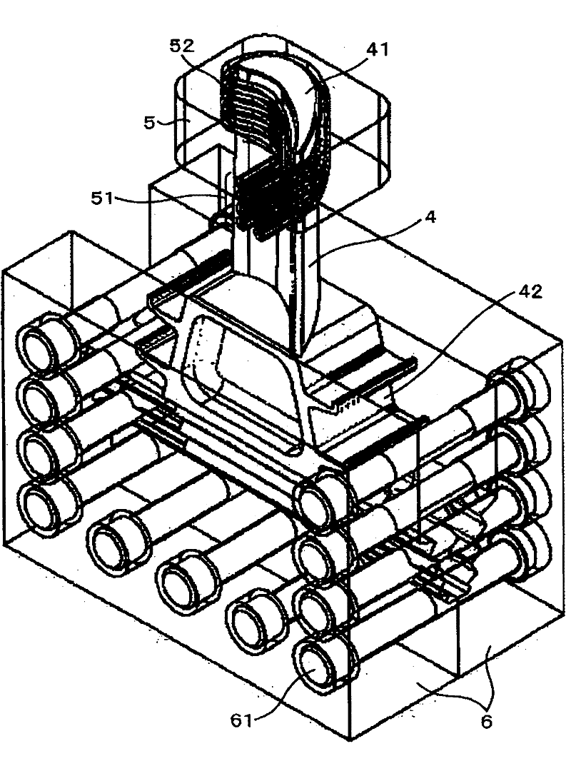
[0038] Figure 4 The usage method of the direct cooling jig 9 for forced cooling at the time of laser overlay welding of Example 2 is shown. 4 denotes single crystal movable blade, 41 denotes construction surface, 42 denotes dovetail groove, 9 denotes direct cooling fixture, 91 denotes refrigerant inlet, 92 denotes refrigerant injection channel, 93 denotes refrigerant shielding plate, 51 denotes refrigerant Introducing and discharging ports, 52 denotes a refrigerant flow path, 6 denotes a movable vane fixing jig, and 61 denotes bolt nuts for connecting the movable vane fixing jig. The single crystal movable blade 4 is fixed to the movable blade fixing jig 6, and the direct cooling jig 9 is assembled on the base material side of the construction part...

Embodiment 3

[0040] Figure 5 The laser deposition welding apparatus of Example 3 is shown. This structure is a structure in which the refrigerant jig 5 is changed to the refrigerant tank 300 in the structure of the first embodiment.

[0041] The refrigerant supplied from the refrigerant supply, circulation and heat exchange device 8 is introduced into the refrigerant tank 300 from the refrigerant inlet 302, and the single crystal alloy 4 fixed to the movable vane fixing jig 6 is arranged in the refrigerant tank 300 and By immersing it in a refrigerant, the single crystal moving vane 4 is directly forcibly cooled, thereby generating a temperature gradient between the construction surface and the base material. At this time, if the single crystal movable vane 4 is immersed in the refrigerant in a manner surrounding the construction surface, the maximum temperature gradient will also be generated in the direction perpendicular to the preferential growth direction of the base material crysta...


PUM


Abstract

The invention provides a metal deposition method and a laser metal deposition apparatus. In the metal deposition method, a buildup is formed on a single crystal or directionally solidified crystal parent material such that the deposition part and the parent material are deposited in the same direction. In a deposition method of forming a buildup on a single crystal or directionally solidified crystal parent material, metal deposition is performed from an extension in a preferential growth orientation of parent material crystals while forcedly cooling a portion of the parent material somewhat below a processed surface and beforehand giving a temperature gradient to the parent material so that a maximum temperature gradient is oriented along the preferential growth orientation of parent material crystals.

Description

technical field [0001] The present invention relates to a surfacing welding method and a laser surfacing welding device used in the surfacing welding method. In the surfacing welding method, in the surfacing welding of an alloy product whose crystal orientation is controlled, the crystal growth orientation of the surfacing part and the base material The solidified crystal orientation of the alloy is the same, and a laminate is formed while performing solidification control. Background technique [0002] A large stress due to centrifugal force is applied to blades of a turbine or a jet engine. Therefore, a blade formed of a unidirectionally solidified alloy or a single crystal alloy having a crystal orientation in the direction in which the centrifugal force acts is used. If the unidirectionally solidified blade or single crystal blade is used for a long time under high temperature and high load environment, oxidation thinning and cracks will occur. In addition, casting def...

Claims


Application Information

Patent Timeline
Patent Type & Authority Applications(China)
IPC IPC(8): B23K26/34B23K26/42B23K26/046B23K26/14B23K31/00
CPCB23K35/0244C30B11/00C30B11/003C30B11/005C30B11/04C30B29/02C30B29/52B23K26/342B23K26/144B23K2101/001B23K2101/34B23K2103/08
Inventor 川中启嗣塚本武志宫城雅德
Owner HITACHI LTD
Why Eureka
Try Eureka