Three-section three-stage-controlled enclosed inner-circulated gas-protected copper wire vacuum quick-cooling annealing furnace

A gas-protected, vacuum-fast technology, applied in furnaces, heat treatment furnaces, furnace types, etc., can solve problems such as blackening of product surfaces, reduction of conductor resistivity, and inability to guarantee temperature control

Inactive Publication Date: 2011-11-09
湘潭高耐合金制造股份有限公司
View PDF3 Cites 14 Cited by
  • Summary
  • Abstract
  • Description
  • Claims
  • Application Information

AI Technical Summary

Problems solved by technology

[0002] At present, domestic electromagnetic wire manufacturers generally use a vacuum well-type annealing furnace to anneal the cold-worked bare copper wire. The purpose is to eliminate cold work hardening, obtain a soft bare copper wire conductor, reduce the conductor resistivity and facilitate subsequent production processes. The existing technical problems mainly include: the first is that the temperature control in the furnace cannot guarantee that the vacuum tank (filling such as CO in the tank after vacuuming) 2 , N 2 Gas and other protective gases to prevent the surface oxidation of bare copper wires during high-temperature annealing, also known as bright annealing treatment) The uniformity of the upper and lower temperatures (the error of the upper and lower temperature of the tank with a height of 2.5m is about 25°C after testing), resulting in The surface hardness of the annealed copper wire is inconsistent, and the mechanical and electrical properties are quite different, which affects the product quality; the second is that the heating process uses the heating element of the furnace to heat the vacuum tank first, and then the heated tank body heats the vacuum tank. Bare copper wire conductors are heated by radiation, and the conductors are mainly heated by conduction, basically there is no convection heating process, resulting in low heating efficiency, long heating time, and poor energy-saving effect; third, the work efficiency is not high, usually a can of copper The total annealing time of the line is about 25 hours from loading → sealing → vacuuming → filling protective gas → heating → heat preservation → air cooling → water cooling to below 50°C, and the whole process of annealing is too long; The control effect of the annealing process is poor, the labor intensity of the workers is high, and the surface of the product is often blackened (oxidized) due to seal leakage during the annealing process, which seriously affects the product quality

Method used


Image

  • Three-section three-stage-controlled enclosed inner-circulated gas-protected copper wire vacuum quick-cooling annealing furnace
  • Three-section three-stage-controlled enclosed inner-circulated gas-protected copper wire vacuum quick-cooling annealing furnace
  • Three-section three-stage-controlled enclosed inner-circulated gas-protected copper wire vacuum quick-cooling annealing furnace

Examples


Embodiment Construction

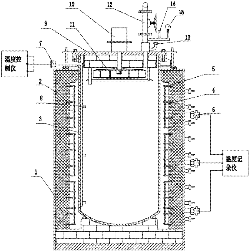
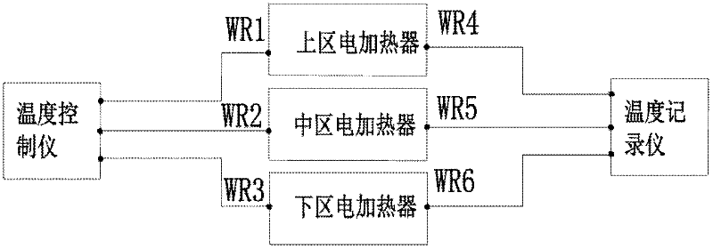
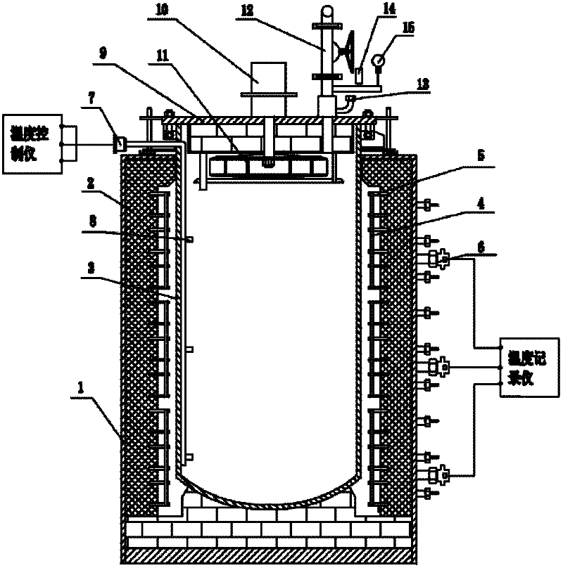
[0009] Such as figure 1 As shown, a three-zone three-control closed-type internal circulation gas protection copper wire vacuum rapid cooling annealing furnace includes a furnace body 1, the inner wall of the furnace body 1 is lined with an insulating layer 2, and a vacuum tank 3 is arranged in the furnace body 1. Tank cover 9 is arranged on vacuum tank 3, and water-cooling fan 10 is arranged on tank cover 9, and vacuum plunger valve 12; There are pressure gauge 14, safety valve 15 and protective gas intake and cooling circulation interface 13. On the inner wall of the insulation layer 2, there are three sections of electric heaters in the upper, middle and lower areas. The electric heaters are fixed on the insulation layer. 2 The corundum nail 5 on the inner wall is composed of the resistance band 4 fixed by the corundum nail 5; the temperature measuring thermocouple 6 is arranged at the electric heater in the upper, middle and lower areas, and the temperature measuring therm...


PUM


Abstract

The invention discloses a three-section three-stage-controlled enclosed inner-circulated gas-protected copper wire vacuum quick-cooling annealing furnace. The furnace comprises a furnace body, a heat-insulating layer coated on the inner wall of the furnace body, a vacuum cylinder arranged in the furnace body, a cylinder cap arranged on the vacuum cylinder, a water-cooling blower arranged on the cylinder cap, and a vacuum plunger valve. Blades of the water-cooling blower are arranged on the inner side of the cylinder cap. An inlet pipe of the vacuum plunger valve is connected to a port for protective gas inletting and for cooling circulating. The inner wall of the heat-insulating layer is divided into an upper section, a middle section and a lower section. Three-stage electric heaters are arranged on the three sections. The electric heaters are composed of corundum nails fixed on the inner wall of the heat-insulating layer and resistor bands fixed with the corundum nails. Temperature measuring thermocouples are arranged at the three sections provided with the electric heaters, and the temperature measuring thermocouples are connected to a temperature recorder. A temperature controlling thermocouple installation pipe is inserted from the outside of the vacuum cylinder to the inner bottom of the cylinder. Three temperature controlling thermocouples are arranged on the part of the temperature controlling thermocouple installation pipe inside the vacuum cylinder. The three temperature controlling thermocouples are arranged corresponding to the positions of the electric heaters arranged in the three sections. The temperature controlling thermocouples are connected to a temperature controller. The annealing furnace has the following functions: (1) over-temperature alarm; (2) open-phase indication; (3) couple breaking indication; (4) water shortage alarm and protection; (5) air pressure lower-limit alarm and powering off; (6) air pressure upper-limit excess automatic exhaustion and pressure reduction by a safety valve; (7) temperature recording with a paperless recorder; (8) a temperature homogeneity equal to or lower than +-3 DEG C; and (9) a temperature controlling accuracy equal to or lower than +-1 DEG C. With the annealing furnace provided by the invention, annealing quality of products is ensured, and labor intensity of workers is reduced.

Description

Technical field [0001] The invention relates to a vacuum annealing furnace Background technique [0002] At present, domestic electromagnetic wire manufacturers generally use a vacuum well-type annealing furnace to anneal the cold-worked bare copper wire. The purpose is to eliminate cold work hardening, obtain a soft bare copper wire conductor, reduce the conductor resistivity and facilitate subsequent production processes. The existing technical problems mainly include: the first is that the temperature control in the furnace cannot guarantee that the vacuum tank (filling such as CO in the tank after vacuuming) 2 , N 2 Gas and other protective gases to prevent the surface oxidation of bare copper wires during high-temperature annealing, also known as bright annealing treatment) The uniformity of the upper and lower temperatures (the error of the upper and lower temperature of the tank with a height of 2.5m is about 25°C after testing), resulting in The surface hardness of...

Claims


Application Information

Patent Timeline
Patent Type & Authority Applications(China)
IPC IPC(8): C21D9/54C21D11/00C21D1/773C21D1/26
Inventor 赵建江国固
Owner 湘潭高耐合金制造股份有限公司
Why Eureka
Try Eureka