A loading fatigue testing machine

A fatigue testing machine and testing machine technology, applied in the field of fatigue testing machines, can solve the problems of no corresponding method, low testing efficiency, high cost, etc., and achieve the effects of stable long-term work performance, improved testing efficiency, and convenient replacement.

Inactive Publication Date: 2011-11-30
CHINA UNIV OF MINING & TECH
View PDF7 Cites 11 Cited by
  • Summary
  • Abstract
  • Description
  • Claims
  • Application Information

AI Technical Summary

Problems solved by technology

The electromagnetic fatigue testing machine has high frequency and small load, which is not suitable for fatigue testing of civil engineering structures; the hydraulic servo fatigue testing machine has advanced technology, high test control accuracy and large load, but it is expensive, power consumption is large, and the machine time is tight , high noise, difficult to be used for long-term fatigue test; mechanical fatigue testing machine is simple in structure, low in cost, low in noise, and has many forms, which is more suitable for long-term fatigue test
Existing mechanical fatigue testing machines generally use motors to actuate and use the principle of leverage or centrifugal force to amplify the power of the motor, but due to the limitation of space and loading system layout, the power magnification is limited, so the load is small
[0004] In addition, most of the existing fatigue loading tests can only test a single specimen at one time, and the test efficiency is low; there are inventions that can realize simultaneous fatigue loading of multiple specimens by setting multiple loading cylinders, but there is no such method in mechanical fatigue testing machines. corresponding method

Method used


Image

  • A loading fatigue testing machine
  • A loading fatigue testing machine
  • A loading fatigue testing machine

Examples


Embodiment 1

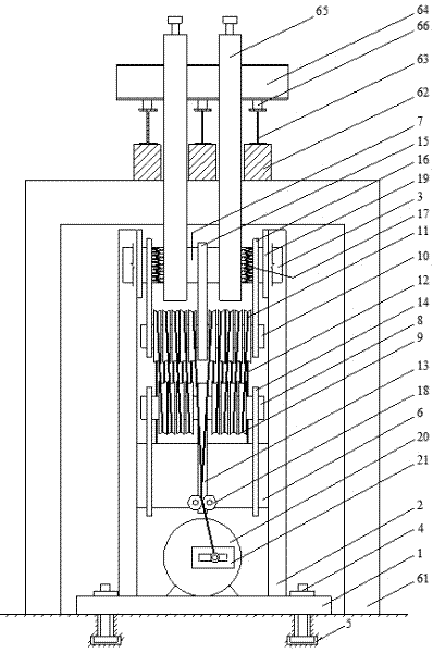
[0018] Embodiment one, as figure 1 Shown is a beam specimen loading testing machine, which is mainly composed of a main engine and a beam specimen reaction force device connected to the main engine. Wherein: the main engine is composed of three parts: an outer frame, a loading mechanism and a power mechanism; the outer frame is composed of a base 1 and a frame 3 arranged on the base 1 . The base 1 is fixedly connected to the trough 5 through the anchor bolt 4; the two frame columns 2 of the frame 3 are channel steel welded with a transverse partition at the top, and two vertical guide keys 19 are arranged on the inner side of the upper part of the two frame columns 2, and the top transverse partition Several connecting screw holes are provided, and the bottom end of the frame column 2 is fixed on the base 1 . The loading mechanism is arranged on the frame 3, and the power machine is arranged under the frame 3 and fixed on the base 1. The loading mechanism is mainly composed ...

Embodiment 2

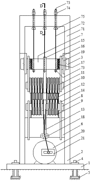
[0020] Embodiment two, such as figure 2 Shown is the steel bar test piece reaction force device testing machine 1. The test machine is mainly composed of a main engine and a steel bar test piece reaction force device connected to the main machine. Wherein the host computer is the same as the first embodiment, and the same parts are omitted. The steel bar test piece reaction force device comprises a steel bar test piece reaction force gantry 71 fixed on the main machine, the steel bar test piece reaction force gantry 71 is a single layer, and the steel bar test piece reaction force gantry 71 is provided with an upper beam A plurality of vertical hole positions on the 7 correspond to a plurality of steel bar holders with the same number of holes for fixing the steel bar test piece 72, and the steel bar holder is provided with a through-hole pressure sensor 74. Rebar anchors such as Figure 5 As shown, it includes a loading bolt 75 that is matched with the thread of the steel ...

Embodiment 3

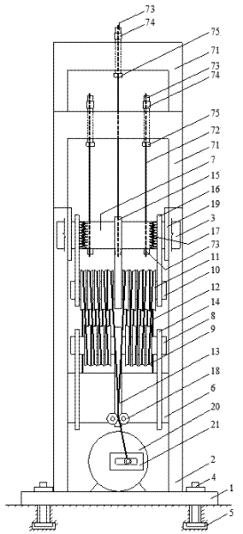
[0023] Embodiment three, as image 3 Shown is the steel bar test piece reaction force device testing machine II, which is basically the same as the second embodiment, and the same parts are omitted. The difference is that the structure of the steel bar test piece reaction gantry 71 is a double-layer structure, that is, the steel bar test piece reaction force device is divided into two layers, the steel bar test piece reaction force device in the middle is arranged on the top layer, and the steel bar test piece reaction force devices on both sides are arranged on the top layer. Symmetry is set on the lower floor. Since the vertical displacement of each specimen is the same, the difference in length must determine the difference in stiffness, which in turn must determine the difference in stress amplitude. Therefore, the multi-frame fatigue loading of the steel bar test piece can be realized by changing the length of the steel bar test piece, and by combining the steel bar test...


PUM


Abstract

The invention discloses a fatigue tester which is suitable for a long-term fatigue performance test of test pieces such as beams, reinforcing steel bars and the like in civil engineering. The fatigue tester mainly comprises four parts, namely a host machine, a beam test piece reaction frame device, a reinforcing steel bar test piece reaction frame and a control system. The host machine is actuated by a motor and provides a reciprocating displacement after a force is amplified and the displacement is shortened by a pulley block. The host machine is respectively matched with a beam test piece reaction frame system or a reinforcing steel bar test piece reaction frame system to finish fatigue loading of two kinds of test pieces; and reciprocating displacement amplitude is adjusted by an eccentric adjuster embedded on a motor shaft. The tester disclosed by the invention has the advantages of simple structure, convenience for processing, assembling, disassembling and replacing, low construction cost and stable long-term work performance; and the fatigue tester can be used for carrying out fatigue loading of multiple test pieces and multiple amplitudes.

Description

technical field [0001] The invention relates to a fatigue testing machine, which is especially suitable for the long-term fatigue performance test of test pieces such as beams and steel bars in civil engineering, and is also suitable for the fatigue performance test of fatigue loads applied to other engineering structural components. Background technique [0002] A large number of civil engineering structures such as bridges, factory buildings, railway station buildings, etc. have been subjected to fatigue loads for a long time, and their components may suffer from brittle fatigue failure. Therefore, it is necessary to conduct fatigue performance tests on these components; at the same time, some structures Still in a corrosive environment, corrosion and fatigue are coupled to form corrosion fatigue, which will cause serious degradation of structural performance of components. At this time, it is necessary to conduct corrosion fatigue performance tests on these components. In...

Claims


Application Information

Patent Timeline
Patent Type & Authority Applications(China)
IPC IPC(8): G01M99/00
Inventor 李富民范力袁迎曙
Owner CHINA UNIV OF MINING & TECH
Why Eureka
Try Eureka