Method for producing coal gas by staged gasification of pulverized coal

A technology for coal gas and pulverized coal, which is applied in the field of coal gasification by pulverized coal classification to produce coal gas, can solve the problems of high production cost, inability to preheat the incoming coal pulverized coal, and high requirements on fineness of coal powder, and achieve flexible adjustment of production load. , the effect of strong coal adaptability and low steel consumption

Inactive Publication Date: 2011-12-14
舒克孝
View PDF3 Cites 23 Cited by
  • Summary
  • Abstract
  • Description
  • Claims
  • Application Information

AI Technical Summary

Problems solved by technology

Its disadvantages: high residual carbon content in coal ash (10% to 30%), strict restrictions on coal types, gasification of high-quality lump coal, resulting in high raw material costs and high production costs for many enterprises. The furnace types mainly include dry exhaust Ash single-stage furnace (GEGas, Lurgi, MERC, etc.), dry ash two-stage furnace (ATC / Wellman, FW-stoic, Ruhr-100), liquid slagging fixed-bed gasifier (BGG / Lurgi , GFETC), producing phenolic water is polluted
Its disadvantages: high equipment investment, large amount of fly ash and high residual carbon content (20% ~ 30%), high residual carbon content in coal ash (5 ~ 15%), that is, the problem of vomiting and diarrhea
Its disadvantages are: high investment in equipment, high requirements for pulverized coal fineness, high energy consumption for pulverization; high reaction temperature (about 1400°C) and short time (a few seconds) but feed pulverized coal cannot be preheated, large oxygen consumption, and energy utilization. Unreasonable, especially the high oxygen consumption of coal water slurry feed and low effective utilization of carbon
Furnace types mainly include K-T coal gasification, Texaco coal gasification, and two-stage entrained bed gasification, which are still being studied in China

Method used


Image

  • Method for producing coal gas by staged gasification of pulverized coal

Examples


Embodiment Construction

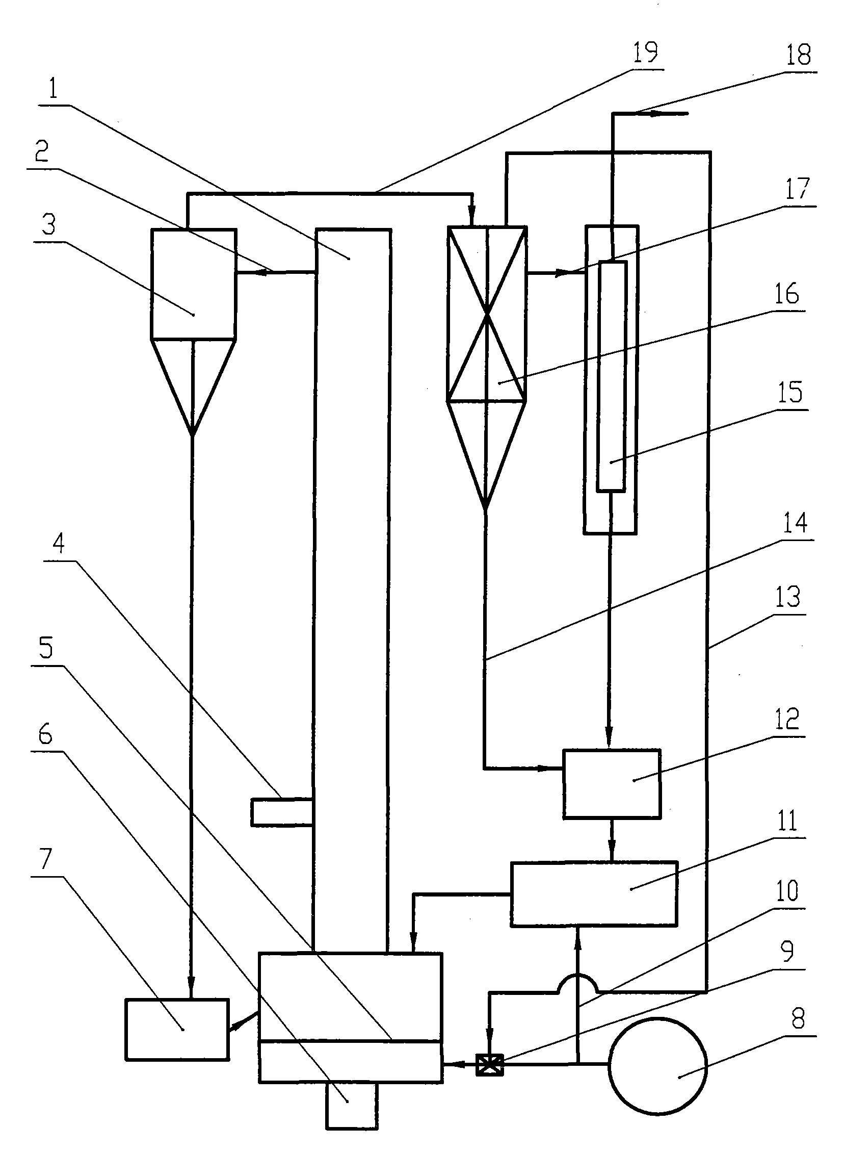
[0013] Qualified pulverized coal less than 10mm and a small amount of limestone and other additives are fed into the middle cavity of the circulating fluidized bed body 1 through the coal inlet 4, and the superheated steam from the superheated steam heat exchanger 16 is fed by the superheated steam pipeline 13 Enter the mixer 9 and mix with the air from the blower 8, as gasification agent and fluidization medium, enter the circulating fluidized bed from the distributor 5 at the bottom of the circulating fluidized bed main body 1, and the pulverized coal into the furnace is mixed with the air in the fluidized bed Rapidly fluidized high-temperature particles and gasification gas are mixed, small and medium-sized coal powder flows upward, pyrolyzed at a high temperature of 900-1000°C, and enter the cyclone separator 3 through the gas-solid mixing pipeline 2 for separation, and the medium particles pass through the first-stage return feeder 7 Return to the lower part of the main bo...


PUM


Abstract

The invention relates to a method for producing coal gas by staged gasification of pulverized coal. The steps are as follows: the pulverized coal fed into the furnace is mixed with rapidly fluidized high-temperature particles and gasification gas in a fluidized bed, and the pulverized coal of small and medium particles flows upwards. Pyrolysis at a high temperature of 900-1000°C, enter the cyclone separator through the gas-solid mixing pipeline for separation, the medium particles return to the lower part of the main body of the circulating fluidized bed through the first-stage feeder, and the gas carries small particles out of the upper port of the cyclone separator, and passes through the high temperature The gas pipeline enters the superheated steam heat exchanger for heat exchange and separation, and then enters the circulation separator, and the gas is discharged from the gas outlet for users. The invention has the characteristics of integrated circulating fluidized bed and entrained flow bed, high gasification intensity, flexible adjustment of production load, stable and reliable operation, high operation rate, reduced gas production cost, and no phenolic water pollution.

Description

technical field [0001] The invention belongs to the field of coal gasification, and in particular relates to a method for producing coal gas by staged gasification of pulverized coal. Background technique [0002] At present, coal gasification technology at home and abroad is mainly divided into: fixed bed block coal gasification technology; circulating fluidized bed pulverized coal gasification technology; entrained bed gasification technology. [0003] Fixed-bed (moving-bed) coal gasification technology is to generate gas from lump coal with air and water vapor. Its advantages are: mature technology, low equipment investment, especially the intermittent fixed bed coal gasification does not require pure oxygen, and the nitrogen-free synthetic gas can be obtained by making gas with water steam and air. Its disadvantages: high residual carbon content in coal ash (10% to 30%), strict restrictions on coal types, gasification of high-quality lump coal, resulting in high raw mat...

Claims


Application Information

Patent Timeline
Patent Type & Authority Applications(China)
IPC IPC(8): C10J3/54C10J3/46C10J3/84C10J3/66C10J3/72
Inventor 舒克孝
Owner 舒克孝
Why Eureka
Try Eureka