A Phase Detector Circuit Applied to Clock Data Recovery

A clock data recovery, phase detector technology, applied in the direction of electrical components, power automatic control, etc., can solve the problem of insufficient phase detector gain of phase detection accuracy, so as to broaden the locking capture range, improve performance, and reduce locking time Effect

Active Publication Date: 2011-12-14
CHANGSHA JINGJIA MICROELECTRONICS
View PDF2 Cites 3 Cited by
  • Summary
  • Abstract
  • Description
  • Claims
  • Application Information

AI Technical Summary

Problems solved by technology

[0004] The data received by the clock data recovery circuit is random data, therefore, the phase detector must also be able to perform phase detection on random data, which is different from the phase detector in the PLL for frequency synthesis, and the phase detector in the CDR To be able to perform phase detection on random data, it must have two functions: first, it can detect data jumps; second, it can detect phase difference. According to the relationship between the output of the phase detector and the phase difference, it can The phase detector is divided into two types: linear phase detector and binary phase detector. Most linear phase detectors are based on the Hogge structure, which outputs an Up or Dn signal whose width is proportional to the phase difference, while the binary phase detector The phase detector is based on the Alexander structure, which outputs an equal-width UP or DN signal according to the relationship between the input data and the clock signal, and the common linear phase detector and binary phase detector have phase detection accuracy. and the problem of insufficient phase detector gain

Method used


Image

  • A Phase Detector Circuit Applied to Clock Data Recovery
  • A Phase Detector Circuit Applied to Clock Data Recovery
  • A Phase Detector Circuit Applied to Clock Data Recovery

Examples


Embodiment Construction

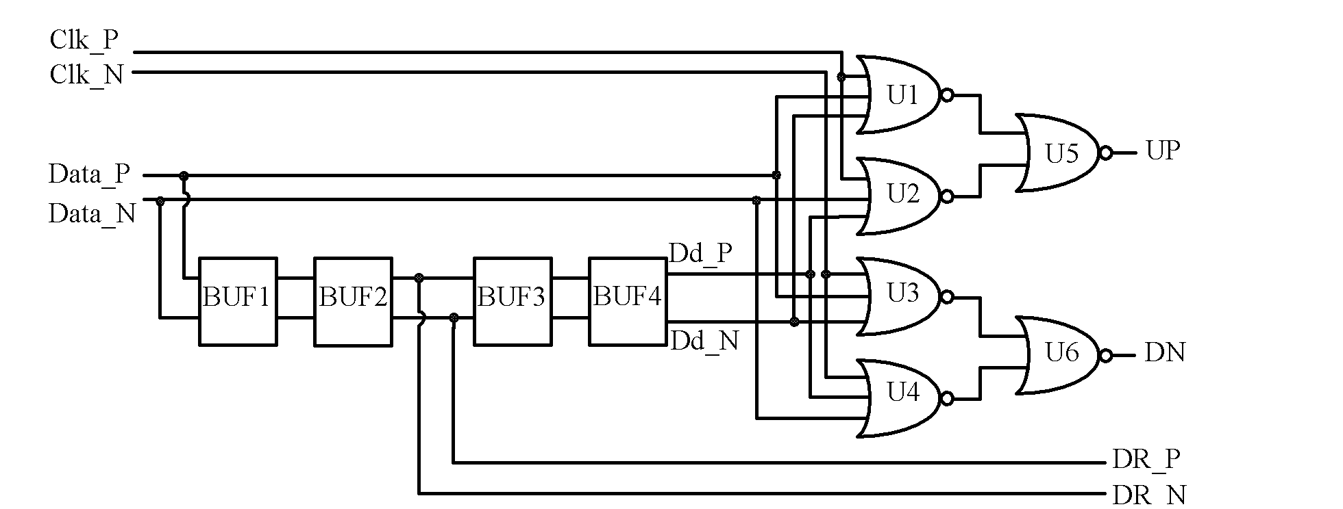
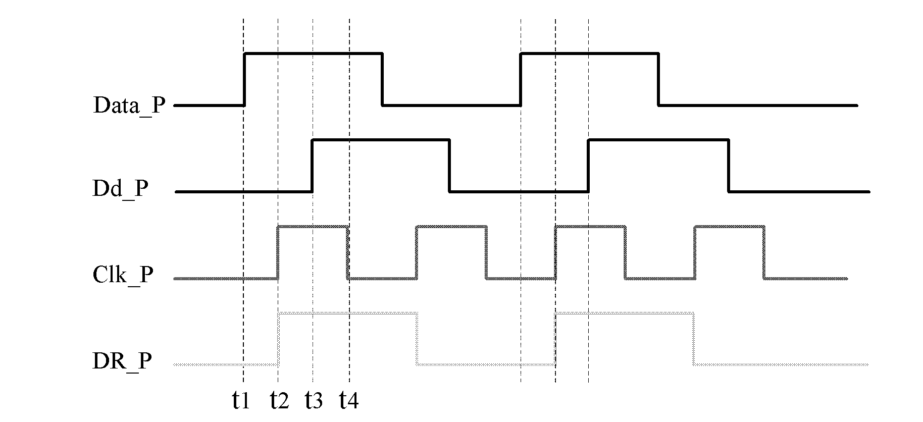
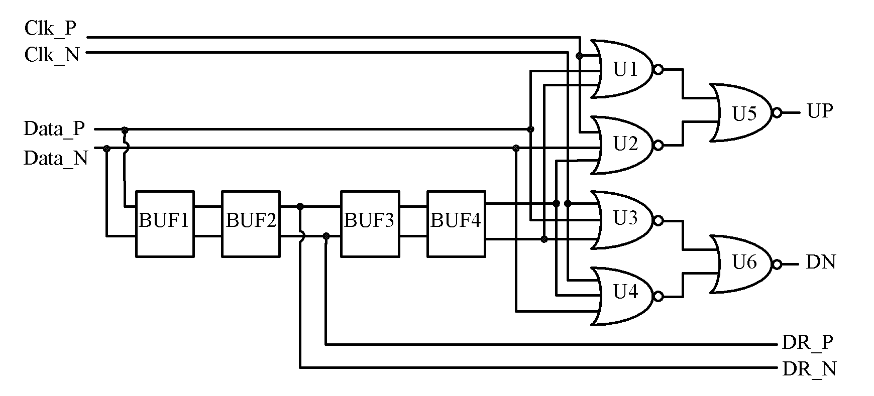
[0013] like figure 1 Shown, the present invention is a kind of phase detector circuit that is applied to clock data recovery, consists of 4 delay buffers BUF1, BUF2, BUF3, BUF4 and 4 three-input NOR gates U1, U2, U3, U4 and 2 Two-input NOR gate U5, U6 is composed, the structure is very simple. Clk_P and Clk_N are differential clock signals, Data_P and Data_N are differential data signals, DR_P and DR_N are signals of Data_P and Data_N after passing through delay buffers BUF1 and BUF2, Dd_P and Dd_N are signals of DR_P and DR_N after passing through delay buffers BUF3 and BUF4 Signals, DR_P and DR_N are the data signals recovered by CDR, Clk_P and Clk_N are the clock signals recovered by CDR, and the goal of CDR is to make the sampling edges of Clk_P and Clk_N in the center of DR_P and DR_N, which is the best sampling point; The output terminal UP of U5 and the output terminal DN of U6 represent the phase lead and phase lag signals respectively, which are used to control the ...


PUM


Abstract

The invention discloses a phase discriminator circuit applied to clock data recovery. The circuit is used for respectively carrying out phase discrimination on a random data signal and a random data delay signal by utilizing a clock signal, judging whether the rising edge of the clock signal is in the midpoint of the rising edges of the random data signal and the random data delay signal so as tooutput a phase advance or lag mark signal and finally realizing the clock data recovery and ensuring that the clock signal after circuit recovery is in an optimal sampling point relative to the recovered data signal; in addition, the phase discriminator performs phase discrimination on two data edges simultaneously by utilizing the clock edges, and the gain of the phase discriminator is two timesmore than that of the common phase discriminator, therefore the loop gain of a clock data recovery circuit is increased, the locking and capturing range is broadened, the locking time is shortened, and the performance of the clock data recovery circuit is improved.

Description

technical field [0001] The invention mainly relates to the field of circuit design for phase detection of random data, in particular to a phase detection circuit applied to clock data recovery. Background technique [0002] The demand for high data bandwidth drives the development of high-speed serial links. A typical link usually includes three parts: transmitter, channel, and receiver. In general design practice, the transmitter and receiver are usually combined Together, called a transceiver, the transceiver plays a very important role in high-speed serial transmission technology, and its bandwidth determines the performance of the high-speed link, and the main difficulty in designing a high-performance transceiver focuses on clock data recovery (Clock Data Recovery, CDR) circuit design. [0003] In high-speed serial transmission technology, the data sender encodes the data and transmits it to the receiver. The sender and the receiver do not have a shared clock signal fo...

Claims


Application Information

Patent Timeline
Patent Type & Authority Applications(China)
IPC IPC(8): H03L7/08H03L7/18
Inventor 蒋仁杰陈怒兴郭斌
Owner CHANGSHA JINGJIA MICROELECTRONICS
Why Eureka
Try Eureka