Performance testing device for piston shoe in axial plunger pump

A technology of axial piston pump and testing device, which is applied in the field of hydraulic components, can solve problems such as the isolation of sliding shoe pairs and errors in test results, and achieve the effects of avoiding interference, less control components, and easy replacement of sliding shoes

Inactive Publication Date: 2012-01-11
HARBIN INST OF TECH
View PDF5 Cites 38 Cited by
  • Summary
  • Abstract
  • Description
  • Claims
  • Application Information

AI Technical Summary

Problems solved by technology

[0005] The purpose of the present invention is to solve the problem that in the prior art, a simulation device is used to simulate and test the performance parameters of the sliding shoes

Method used


Image

  • Performance testing device for piston shoe in axial plunger pump
  • Performance testing device for piston shoe in axial plunger pump
  • Performance testing device for piston shoe in axial plunger pump

Examples


specific Embodiment approach 1

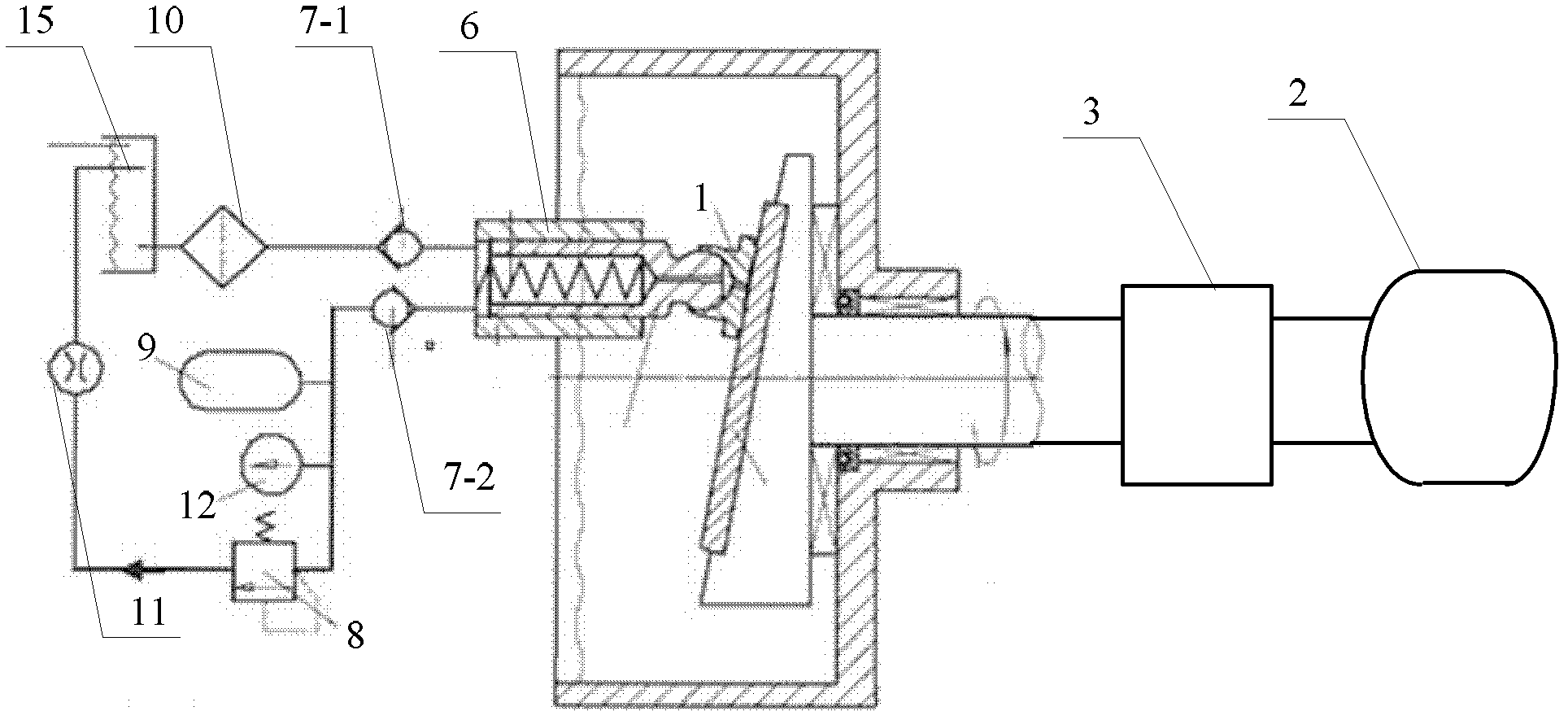
[0030] Specific implementation mode one: the following combination Figure 1 to Figure 10 Describe this embodiment, the test device for the performance of the sliding shoe in the axial piston pump described in this embodiment, it includes a sliding shoe 1, characterized in that: it also includes a frequency conversion motor 2, a speed torque sensor 3, a variable device, a hydraulic cylinder Body 5, plunger 6, flow meter 11, pressure gauge 12, oil tank 15 and temperature sensor 16,

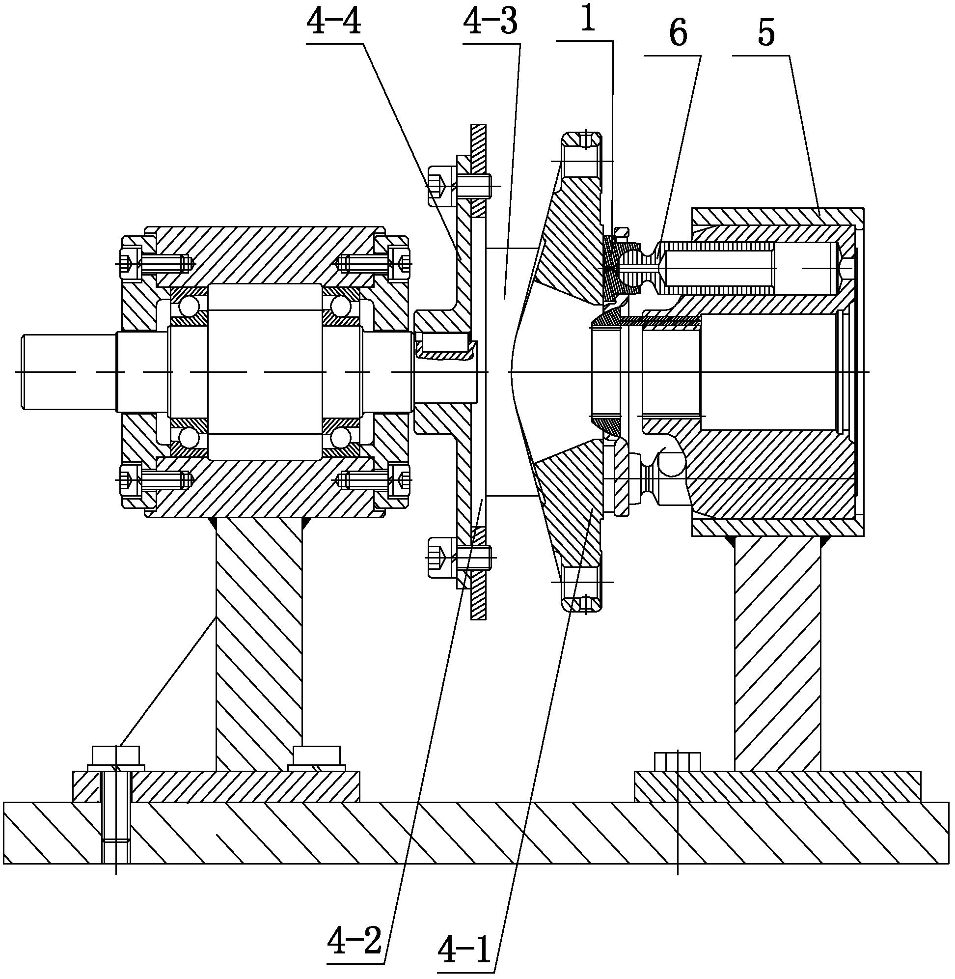
[0031] The variable device is composed of a swash plate 4-1, a swash plate support tile 4-2, two fastening splints 4-3 and a shaft joint plate 4-4,

[0032] The shaft connecting plate 4-4 and the bottom plate of the swash plate support tile 4-2 are fixedly connected by bolts, the swash plate 4-1 is supported by the swash plate support tile 4-2, and the clamping plate 4-3 is provided with three threaded holes and a Waist-shaped groove, two fastening splints 4-3 are respectively arranged on both sid...

specific Embodiment approach 2

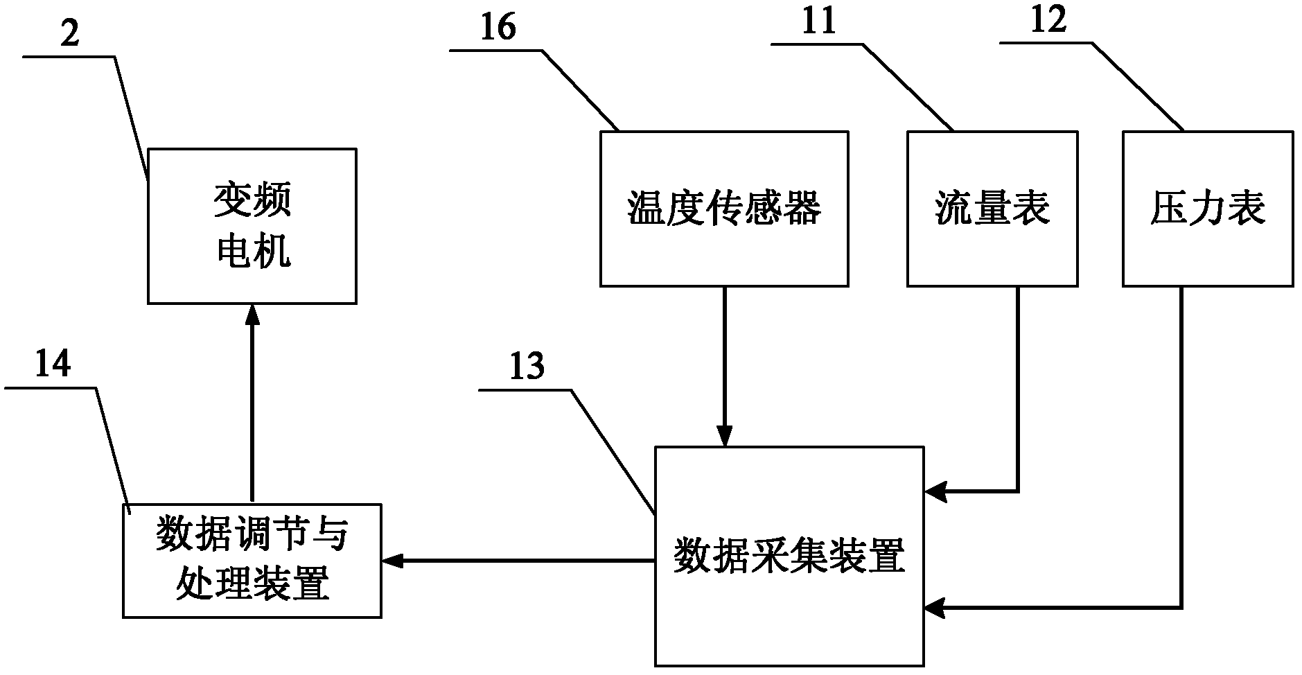
[0044] Specific implementation mode two: the following combination figure 2 Describe this embodiment, this embodiment is a further description of Embodiment 1, this embodiment also includes a data acquisition device 13 and a data adjustment and processing device 14,

[0045] The temperature data output end of the temperature sensor 16 is connected to the temperature data input end of the data acquisition device 13, the flow data output end of the flow meter 11 is connected to the flow data input end of the data acquisition device 13, and the pressure data output end of the pressure gauge 12 is connected to the data acquisition device The pressure data input end of 13, the data output end of data acquisition device 13 is connected with the data input end of data adjustment and processing device 14,

[0046] The motor control signal output end of the data adjustment and processing device 14 is connected to the control signal input end of the variable frequency motor 2 .

[004...

specific Embodiment approach 3

[0049] Specific implementation mode three: the following combination figure 1 Describe this embodiment, this embodiment is a further description of Embodiment 1 or 2, this embodiment also includes a first check valve 7-1, between the oil inlet of hydraulic cylinder block 5 and the oil outlet of oil tank 15 A first one-way valve 7-1 is arranged on the communication pipeline of the.


PUM


Abstract

A performance testing device for a piston shoe in an axial plunger pump belongs to the technical field of hydraulic elements, and solves the problems that in the prior art a simulator is adopted to carry out the simulation test on the performance parameter of the piston shoe in the plunger pump, the test result has errors, and a piston shoe pair is difficult to be isolated from other friction component pairs when the performance parameter test is carried out in the piston shoe in a practical pump. The performance testing device for the piston shoe in the axial plunger pump comprises a piston shoe, and further comprises a variable frequency motor, a rotating speed and torque sensor, a variable device, a hydraulic cylinder body, a plunger, a flowmeter, a pressure gauge, an oil box and a temperature sensor, wherein the coupling plate of the variable device is fixedly connected with a bottom plate of a support tile of a swash plate through a bolt, the swash plate is supported by the support tile of the swash plate, three screwed holes on each fastening splint are connected with three corresponding screwed holes on one side of the swash plate through the bolts, a waist-shaped slot on each fastening splint corresponds to and is connected with the screwed hole on the side wall of the support tile of the swash plate through bolts, so the swash plate can swing in the support tile of the swash plate. The performance testing device for the piston shoe in the axial plunger pump is used for testing the performance of the piston shoe in the axial plunger pump.

Description

technical field [0001] The invention relates to a test device for the performance of a sliding shoe in an axial piston pump, which belongs to the technical field of hydraulic components. Background technique [0002] The hydraulic pump is an indispensable energy component in hydraulic equipment. Its main function is to convert the mechanical energy of the prime mover into hydraulic energy and provide liquid with a certain pressure and flow to the hydraulic system. With the continuous development of hydraulic transmission technology, hydraulic pumps are also developing in the direction of high speed, heavy load and high power. The pump with high efficiency, wide speed range, large transmission power, good bidirectional variable capacity and long life is also the first in all types of hydraulic pumps in terms of structural complexity and manufacturing cost. However, the requirements of ultra-high pressure and large flow rate have also brought a series of problems to the desig...

Claims


Application Information

Patent Timeline
IPC IPC(8): F04B51/00
Inventor 姜继海孙毅代晶辉刘成强
Owner HARBIN INST OF TECH
Why Eureka
Try Eureka