
Coal gasification method

A technology for coal gasification and coal gas flow, which is applied in the field of coal gasification technology, can solve the problems of high unconverted carbon content and low operating temperature, and achieve the effects of improving gasification efficiency, increasing gasification temperature, and easily expanding capacity.

Inactive Publication Date: 2012-03-14
INST OF PROCESS ENG CHINESE ACAD OF SCI +2
View PDF4 Cites 16 Cited by
  • Summary
  • Abstract
  • Description
  • Claims
  • Application Information

AI Technical Summary

Problems solved by technology

However, the disadvantages of the conventional fluidized bed are: 1) to prevent slagging, the operating temperature is low (850 ° C ~ 950 ° C), so it is only suitable for lignite and high-activity bituminous coal; The amount is relatively high (up to about 10% of the coal amount), and another boiler must be installed for combustion
This process needs to control the reaction temperature of the second stage, which is easy to produce coal tar

Method used


Image

  • Coal gasification method
  • Coal gasification method
  • Coal gasification method

Examples


Embodiment 1

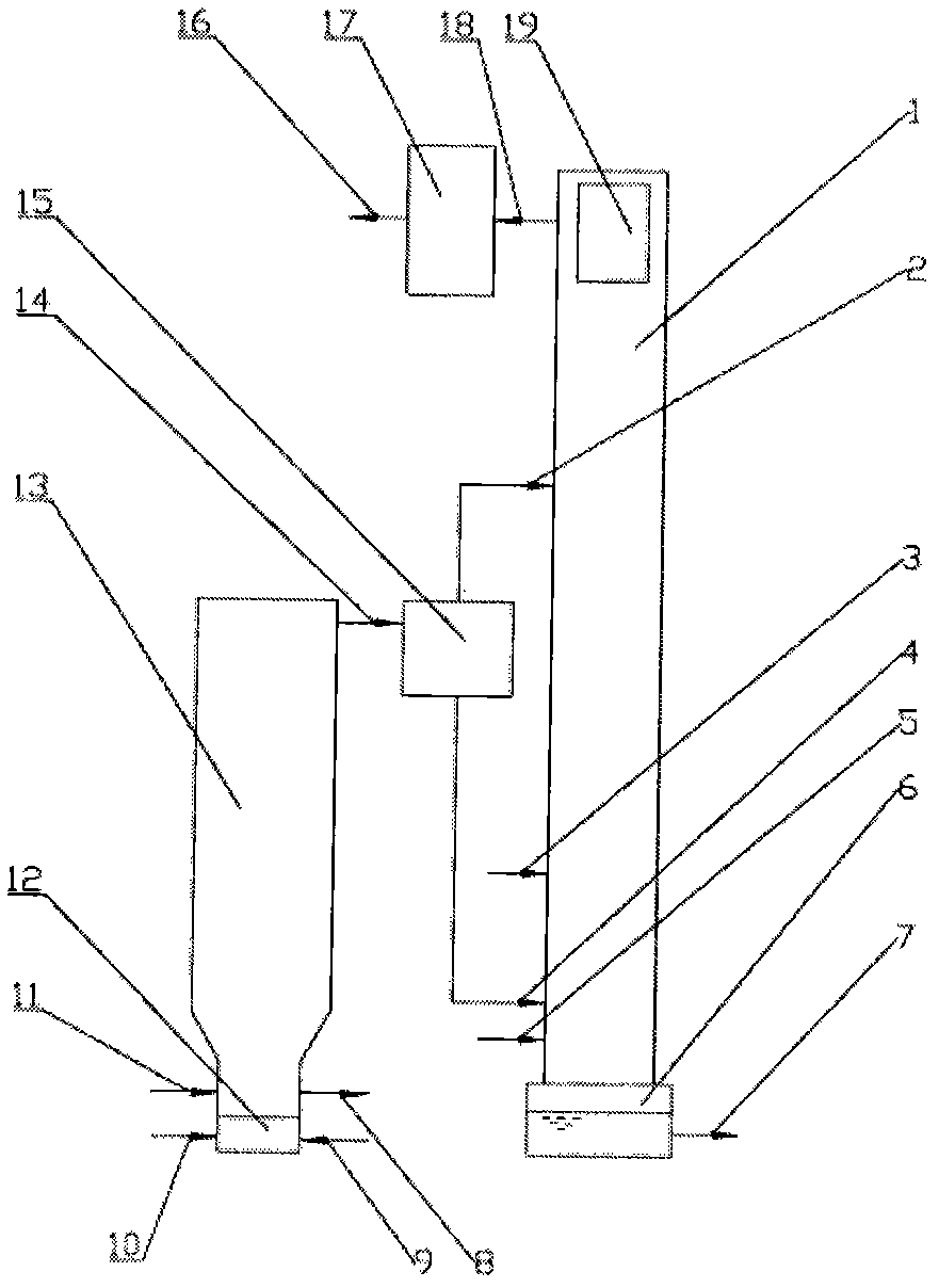
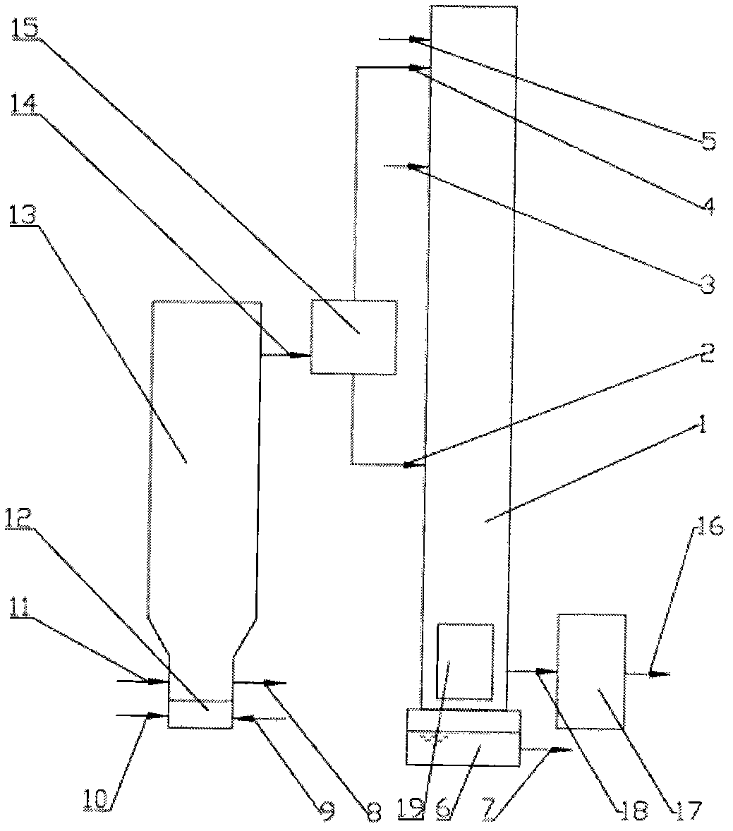
[0067] Such as figure 1 As shown in the process flow chart, the raw coal is fed into the lower space of the fluidized bed gasification furnace 13 through the coal inlet 11, and the molar ratio of hot air and steam at a temperature of 100-800°C is 3:1-15:1, and the fluidized The hot air pipe 10 of the bed gasifier and the steam pipe 9 of the fluidized bed gasifier enter the air distribution chamber 12, and then enter the lower space of the fluidized bed gasifier 13 from the air distribution chamber 12. The oxygen content of the hot air is between the oxygen content of pure air and pure oxygen (that is, 21% to 99.2% by mole, preferably 21% to 75%), and the oxygen content required for raw coal gasification is the same as It is related to the coal quality analysis of coal. Generally, the molar ratio of oxygen to carbon is 0.9-1. The hot air and steam undergo violent heat exchange and chemical reaction in the lower space of the fluidized bed gasifier 13 in the range of 850-1000°C,...

Embodiment 2

[0078] Such as figure 2 As shown in the process flow chart, the raw coal is fed into the lower space of the fluidized bed gasifier 13 through the coal inlet 11, and the molar ratio of oxygen and steam at a temperature of 100-800°C is 1-3, and the oxygen and steam of the fluidized-bed gasifier are supplied respectively. The pipe 10 and the steam pipe 9 of the fluidized bed gasifier enter into the air distribution chamber 12, and then enter the lower space of the fluidized bed gasifier 13 from the air distribution chamber 12. Oxygen and steam undergo intense heat exchange and chemical reactions in the lower space of the fluidized bed gasifier 13, and the generated gas carries small particles of coal and ash up to the upper space of the fluidized bed gasifier 13 with the air flow to continue the reaction. The reaction temperature is 800 In the range of ~2000°C, part of the ash is discharged out of the furnace through the slag discharge pipe 8 of the fluidized bed gasifier. The ...


PUM


Abstract

The invention provides a fluidized bed-entrained flow bed gas gasification method. The method comprises the following steps: 1) carrying out reaction on raw material coal and a mixture of air and steam or a mixture of oxygen and steam to obtain gas containing incompletely reacted coal and ash; 2) separating the gas obtained from the step 1) to obtain condensed fine coal air-flow and light fine coal air-flow, and carrying out reaction on the condensed fine coal air-flow with air or oxygen to obtain gas containing coal and ash; 3) carrying out reaction on the gas obtained from the step 2) and steam to obtain gas containing coal and ash; 4) carrying out reaction on the gas obtained from the step 3), the light fine coal air-flow separated from the step 2) and a mixture of steam and carbon dioxide to obtain final gas containing coal and ash. The method lowers investment and operating cost of a traditional pulverizing system by an entrained flow bed gasification method and has a substantially increased gasification temperature than a traditional fluidized bed gasification method, so as to reduce equipment cost and increase gasification efficiency.

Description

technical field [0001] The invention belongs to the field of coal gasification technology, and relates to a coal gasification method, in particular to a novel fluidized bed-entrained bed gasification coal gasification which combines fluidized bed gasification and entrained bed gasification to improve gasification efficiency and reduce costs method. Background technique [0002] Modern industrial coal gasification processes mainly include fixed bed gasification, fluidized bed gasification and entrained bed gasification. [0003] Fixed bed gasification must use lump coal (6 ~ 50mm). Coal and gasification agent flow countercurrently, cold coal enters and cold gas flows out, which is beneficial to reduce oxygen consumption in the gasification process and improve gasification efficiency. However, on the other hand, in order to prevent the ash sintering in the gasification process, the amount of steam used is relatively large, which causes a large consumption of sensible heat in...

Claims


Application Information

Patent Timeline
IPC IPC(8): C10J3/46C10J3/48C10J3/56C10J3/54
Inventor 郝江平高士秋蔡连国许光文沈勇彪
Owner INST OF PROCESS ENG CHINESE ACAD OF SCI
Learn More