Two-row rare earth continuous gas carburization furnace carburization medium flow rate disc
A carburizing medium and gas carburizing technology, which is applied in the direction of metal material coating process, coating, solid diffusion coating, etc., can solve the cost of easy leakage of ammonia gas and carburizing medium, easy occurrence of non-martensitic structure, Reduce the service life of the workpiece and other issues, to achieve the effect of reducing deformation, low operating cost and prolonging the service life
- Summary
- Abstract
- Description
- Claims
- Application Information
AI Technical Summary
Problems solved by technology
Method used
Image
Examples
specific Embodiment approach 1
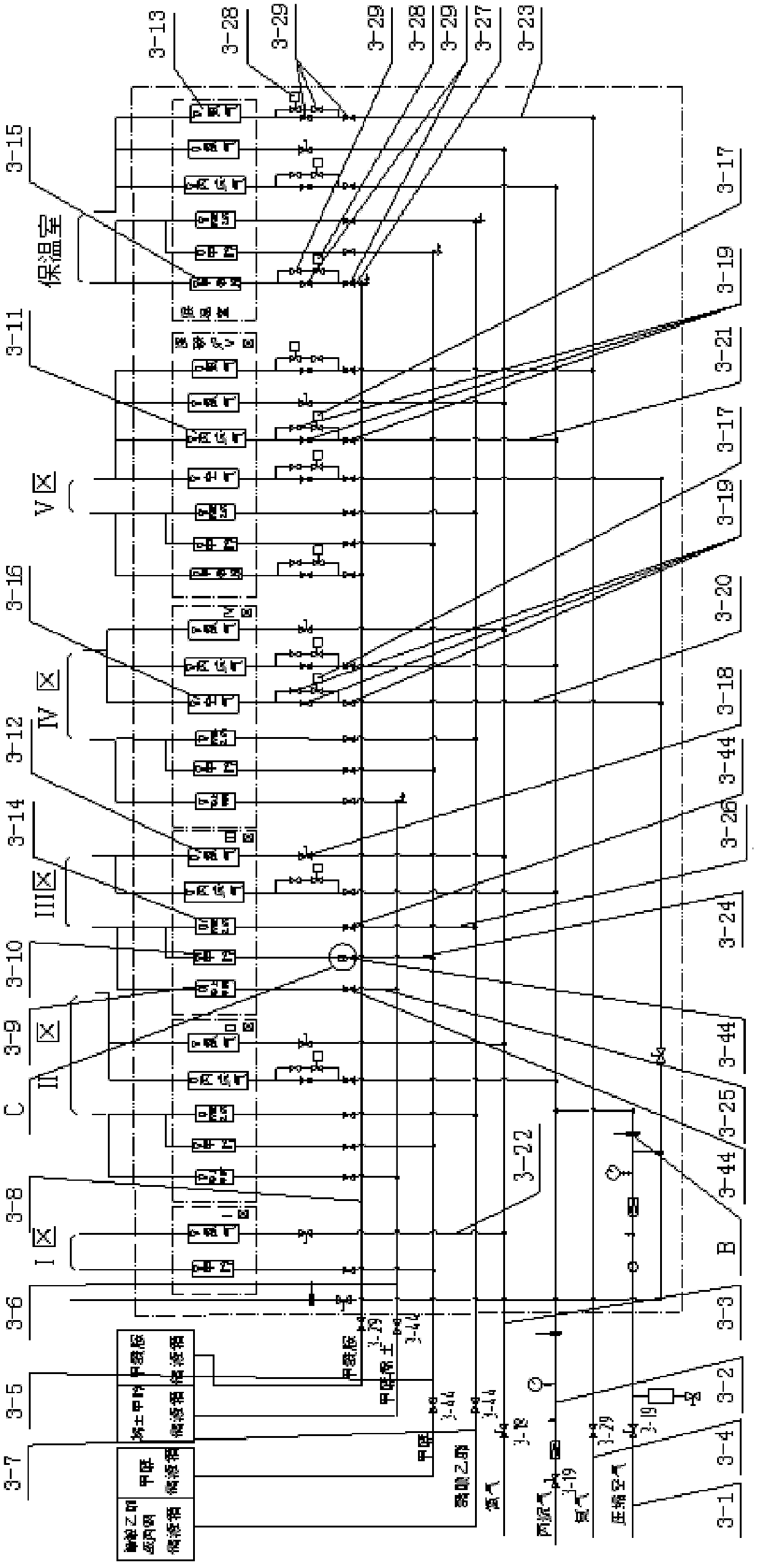
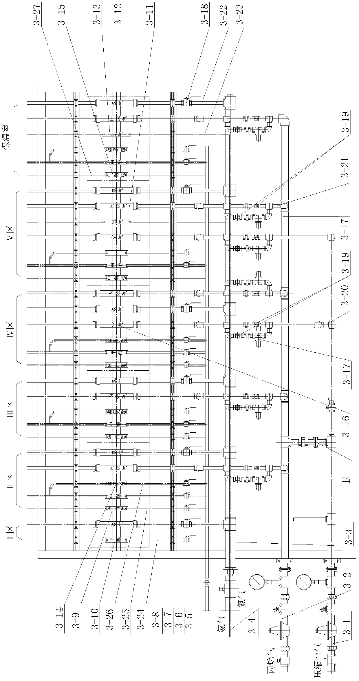
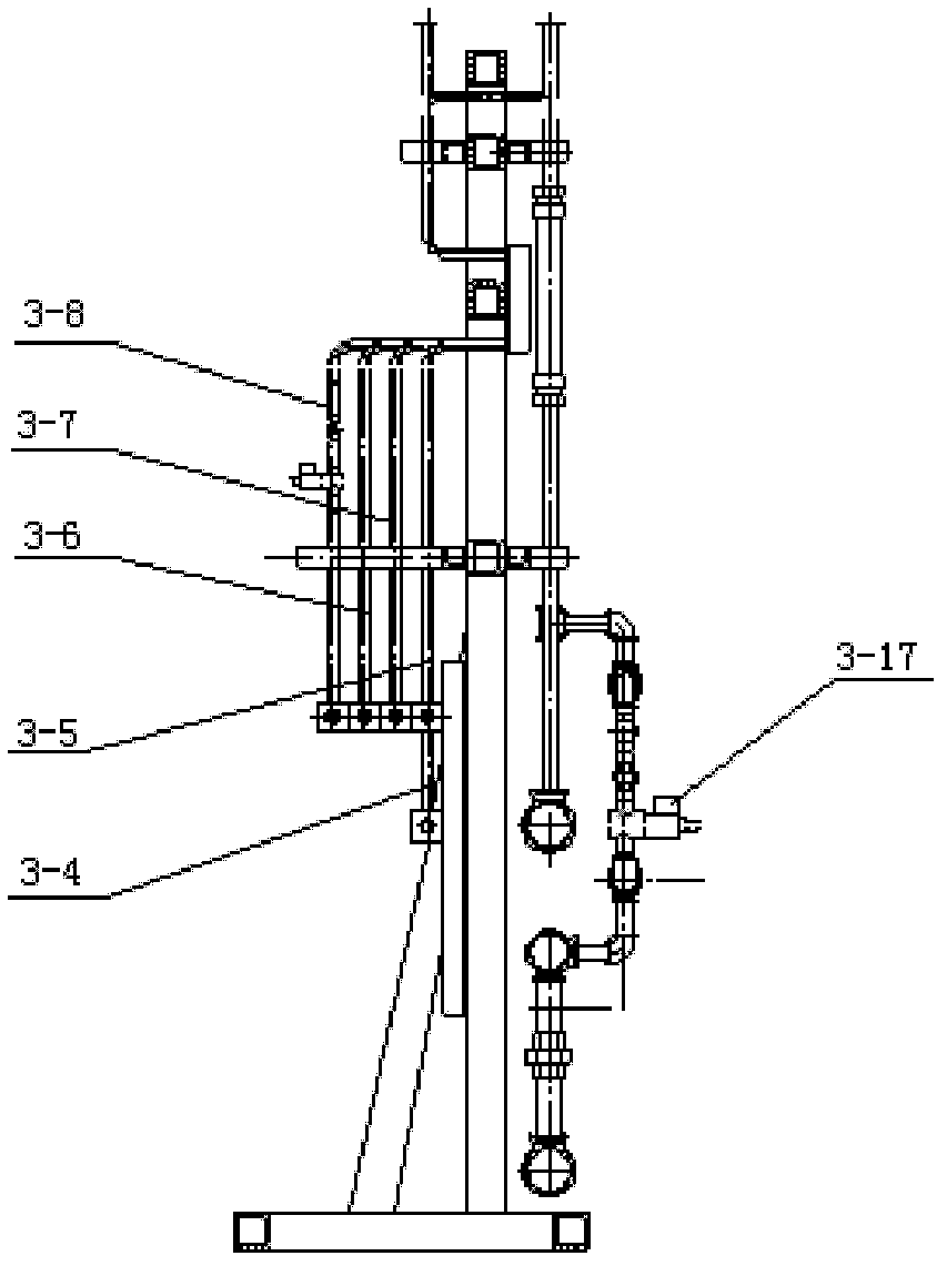
[0008] Specific implementation mode one: combine figure 1 , figure 2 , image 3 , Figure 4 , Figure 5 The present embodiment will be described. This embodiment consists of compressed air pipeline 3-1, propane pipeline 3-2, nitrogen pipeline 3-3, ammonia pipeline 3-4, methanol pipeline 3-5, rare earth methanol pipeline 3-6, ethyl acetate pipeline Ester or acetone pipeline 3-7, formamide pipeline 3-8, rare earth methanol flowmeter 3-9, methanol flowmeter 3-10, propane flowmeter 3-11, nitrogen flowmeter 3-12, ammonia flowmeter 3-13, ethyl acetate or acetone flowmeter 3-14, formamide flowmeter 3-15, air flowmeter 3-16, solenoid valve 3-17, stainless steel solenoid valve 3-28, ball valve 3-18, stainless steel ball valve 3-44. Composed of internal thread plug valve 3-19 and welded ammonia valve 3-29, a compressed air branch 3-20 is provided on the compressed air pipeline 3-1, and a compressed air branch 3-20 is provided on the propane pipeline 3-2. Propane branch 3-21, nitr...
specific Embodiment approach 2
[0009] Specific implementation mode two: combination Figure 5 , Image 6The present embodiment will be described. The welded tee pipe joint 3-45 described in this embodiment consists of a steel pipe 3-45-1, a connecting pipe 3-45-2, a nut 3-45-3, an O-ring seal 3-45-4, and a type A The three-way joint body 3-45-5 is composed of one end of the connecting pipe 3-45-2 welded with the steel pipe 3-45-1, and the other end of the connecting pipe 3-45-2 is connected with the A-type tee joint body 3-45-5 An O-ring 3-45-4 is arranged between adjacent ends of the pipe, and the other end of the connecting pipe 3-45-2 is connected with the A-type tee joint body 3-45-5 by a nut 3-45-3.
specific Embodiment approach 3
[0010] Specific implementation mode three: combination Figure 5 , Figure 7 The present embodiment will be described. The welded right-angle pipe joint 3-46 described in this embodiment is composed of a steel pipe 3-46-1, a connecting pipe 3-46-2, a nut 3-46-3, an O-shaped sealing ring 3-46-4, and an A-shaped right-angle pipe joint. The joint body is composed of 3-46-5, one end of the connecting pipe 3-46-2 is welded with the steel pipe 3-46-1, and the other end of the connecting pipe 3-46-2 is adjacent to the A-type right angle joint body 3-46-5 An O-ring 3-46-4 is arranged between one end of the pipe, and the other end of the connecting pipe 3-46-2 is connected with the A-type right-angle joint body 3-46-5 by a nut 3-46-3.
PUM
 Abstract
Description
Claims
Application Information
 - R&D
- Intellectual Property
- Life Sciences
- Materials
- Tech Scout
- Unparalleled Data Quality
- Higher Quality Content
- 60% Fewer Hallucinations
Browse by: Latest US Patents, China's latest patents, Technical Efficacy Thesaurus, Application Domain, Technology Topic, Popular Technical Reports.
© 2025 PatSnap. All rights reserved.Legal|Privacy policy|Modern Slavery Act Transparency Statement|Sitemap|About US| Contact US: help@patsnap.com


