Method for preparing ultrathin carbon film by using carbon cluster ion beam

An ion beam and cluster technology, applied in the field of nanomaterials, can solve the problems of difficulty in large-area production of graphene, difficulty in controlling ion energy, inability to guarantee monopotency, etc., achieving precise and controllable dose, good uniformity, Preparing convenient effects

Inactive Publication Date: 2012-03-14
WUHAN UNIV
View PDF3 Cites 7 Cited by
  • Summary
  • Abstract
  • Description
  • Claims
  • Application Information

AI Technical Summary

Problems solved by technology

These ions cannot be analyzed by the electromagnetic field, so the energy range is very large, it is difficult to control the ion energy deposited on the substrate, and its monopotency cannot be guaranteed, and the focused ion beam device can only operate in a small area, which is difficult to meet the large-scale production of graphite. ene requirements

Method used


Image

  • Method for preparing ultrathin carbon film by using carbon cluster ion beam
  • Method for preparing ultrathin carbon film by using carbon cluster ion beam
  • Method for preparing ultrathin carbon film by using carbon cluster ion beam

Examples


Embodiment 1

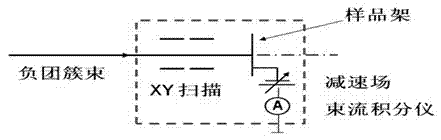
[0021] Example 1: No scanning electric field, only acceleration and deceleration electric field

[0022] When no target rack is placed in the deposition target chamber, the gate valve 12 is in the "off" state at this time, and the vacuum degree before the deposition target chamber is better than 7×10 -4 Pa. Because there is a small vacuum valve connected between the plexiglass layer 10 of the target frame and the connecting pipe 11, when installing the target frame into the deposition target chamber, it is necessary to pre-evacuate properly and open the gate valve 12 ("on" state) The separated target frame can rotate the copper rod 8, the fixed connecting pipe 9, and the plexiglass layer 10 to be easily manually rotated to the center of the deposition target chamber (try to make the normal line of the substrate plane on the frontmost aluminum target and the distance between the cluster beam flow The direction remains parallel), and the actual position of the target surface c...

Embodiment 2

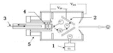
[0027] Embodiment 2: Acceleration and deceleration electric field, plus scanning electric field

[0028] The operation steps of the acceleration and deceleration electric field in scheme 2 are similar to scheme 1, except that when the electric field needs to be scanned in the XY direction, due to safety considerations, preliminary preparations must be made. When using a dual-channel AC power supply instead of a DC power supply to apply voltage to the coaxial scanning device, select the X-axis and Y-axis directions corresponding to the 7 scanning electrodes, and select an appropriate dual-channel output voltage, such as 5kV.

[0029] In the vertical direction of the normal line of the target frame plane, that is, when the voltage in the X-axis or Y-axis direction is added in the vertical direction around the beam current, the actual measured scanning voltage value can be determined by measuring the high-voltage electric meter, which can make the beam current After the decel...

Embodiment 3

[0033] Because the plexiglass layer 17 of the target frame design is too close to the beam integrator measuring clip 15, when a high voltage of 10 kV or more is applied, it is easy to generate discharge and burn out the instrument; moreover, in order to better suppress the secondary electrons In order to avoid the influence of flow measurement, it is necessary to apply suppression voltage on the target. In view of these two limitations, we optimized the design of the details of the target frame, such as Image 6 .

[0034] The optimized position is as follows:

[0035] 1) Change the thickness of the original 40mm plexiglass layer to 70mm in 17 places

[0036] 2) Fix an electrode 16 through the plexiglass layer of 70mm, connect it with the connecting electrode at 20 with a good wire, and add a suppression voltage of 220V at 24

[0037] 3) 21 20mm plexiglass layers insulate the suppression electrode cover from the tetrahedral aluminum target

[0038] 4) 22 windows are opened t...


PUM


Abstract

The invention provides a method for preparing an ultrathin carbon film. A small carbon cluster negative ion beam is produced by sputtering a graphite target with cesium ions, and the ultrathin carbon film is formed by scanning and depositing the small carbon cluster negative ion beam on the surface of a base material through a magnetic retarding field in proper vacuum conditions. The device mainly comprises an ion source, a scanner, a deposition target chamber and a vacuum system, wherein the ion source, the scanner and the deposition target chamber are successively connected and are in the vacuum system. The energy of the carbon cluster negative ion beam produced by the ion source is reduced from ten-odd of KeV to tens or hundreds of eV, and the ultrathin carbon film with uniform thickness is formed on the substrate through scanning. In the invention, the advantages of low energy and accurate and controllable dosage of the low-energy cluster negative ion beam are utilized, and the ultrathin carbon film is prepared by using the direct deposition method.

Description

technical field [0001] The invention relates to a method for preparing an ultra-thin carbon film by using a carbon cluster ion beam, belonging to the field of nanometer materials. Background technique [0002] Graphene, as a typical ultra-thin carbon film, is a two-dimensional crystal composed of closely packed carbon atoms. Due to its good physical singularity and electrical properties, it has a bright future in the application of semiconductor functional devices. Graphene has a carrier concentration and mobility much higher than that of single crystal silicon, and is little affected by temperature and doping. The transport of carriers is not affected by lattice defects and impurity atom scattering, showing submicron Scale ballistic transfer properties. At present, the effective methods for preparing graphene are (1) mechanical cleavage of graphite: graphene with a thickness of one or several atomic layers can be prepared, and large-area film formation is difficult to ach...

Claims


Application Information

Patent Timeline
IPC IPC(8): C23C14/46C23C14/06
Inventor 王泽松王世旭张早娣付德君
Owner WUHAN UNIV
Why Eureka
Try Eureka