Folded lasers system
A laser system, folding technology, applied in lasers, semiconductor lasers, laser parts and other directions, can solve problems such as reduction, achieve the effect of loose alignment tolerance and minimized temperature gradient
- Summary
- Abstract
- Description
- Claims
- Application Information
AI Technical Summary
Problems solved by technology
Method used
Image
Examples
example 1
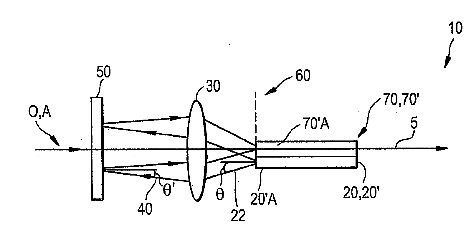
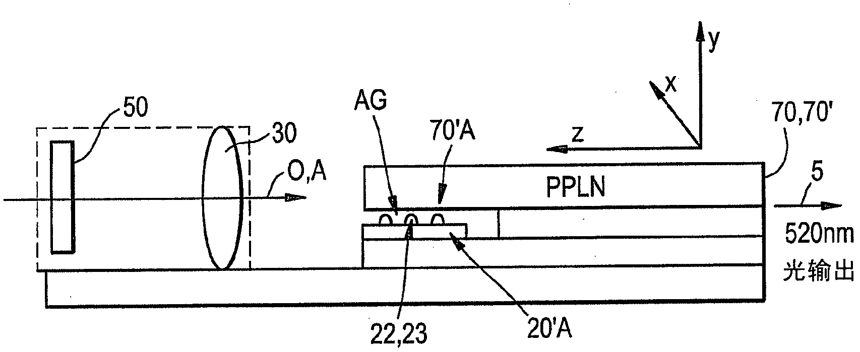
[0066] Figure 14 Shows Figure 11 Lens assembly 30 is shown. In this exemplary embodiment, figure 2 and 3 The lens assembly 30 is optimized to provide an RMS (root mean square) wavefront error (WFE) of less than 0.1λ for a ±200 μm field at a wavelength of 1060 nm at a numerical aperture NA of 0.4, and is optimized to have focal length and thickness The combination makes the optical path length between light source and receiver 9.36mm.
[0067] The radius of curvature of the lens assembly 30 (r 1 , r 2 ), thickness Th (vertex to vertex), and aspheric coefficients are chosen to have the following advantages:
[0068] 1. Minimize coma and astigmatism, (the two most serious aberrations for system performance);
[0069] 2. Obtain a large field of view: the combination of low field aberration and large aperture (for example, NA=0.4) makes the laser system for 400 μm (d =350μm, ±25μm) spacing has good coupling efficiency; and
[0070] 3. Provide the appropriate combination...
example 2
[0082] Figure 16 Another exemplary lens assembly 30 suitable for use in laser system 10 is shown. Figure 16 The lens assembly 30 has the following features:
[0083] (I) It allows the laser system to be in a coupled cavity state (the OPL between the diode laser and the nonlinear laser system is equal to the OPL of the diode laser, and the error is within + / -0.05mm);
[0084] (II) and with the following parameters: (i) FWD = 0.568 mm; (ii) thickness Th (apex to apex) of 1.82 mm; (iii) focal length: f = 1.4 mm; (iv) glass refractive index N at 1060 nm is 1.784;
[0085] (v) NA=0.4.
[0086] Figure 16 The surface parameters of the lens assembly 30 are given in Table 2 below.
[0087] Table 2
[0088] wavelength
[0089]
example 3
[0091] Figure 17 A lens assembly 30 suitable for use in laser system 10 is shown. figure 2 and 3 The lens assembly 30 has the following features:
[0092] (I) It allows the laser system to be in a coupled cavity state (the OPL between the diode laser and the nonlinear laser system is equal to the OPL of the diode laser, and the error is within + / -0.05mm);
[0093] (II) and with the following parameters: (i) FWD = 1.01 mm; (ii) thickness Th (apex to apex) of 1.578 mm; (iii) focal length: f = 1.789 mm; (iv) glass refractive index N at 1060 nm is 1.5; (v) NA=0.4.
[0094] Figure 17 The surface parameters of the lens assembly 30 are given in Table 3 below.
[0095] table 3
[0096] Aspheric parameters
[0097] Sag
[0098] Sag=Ch^2 / (1+((1-(1+K)×C^2×h^2))^0.5)+A4h^4+A6h^6+…+A16h^16
[0099] h; radius
[0100] wavelength
1060
1.578
Refractive index at 1060nm
1.502905
focal length
1.789
FWD
...
PUM
 Abstract
Description
Claims
Application Information
 - R&D
- Intellectual Property
- Life Sciences
- Materials
- Tech Scout
- Unparalleled Data Quality
- Higher Quality Content
- 60% Fewer Hallucinations
Browse by: Latest US Patents, China's latest patents, Technical Efficacy Thesaurus, Application Domain, Technology Topic, Popular Technical Reports.
© 2025 PatSnap. All rights reserved.Legal|Privacy policy|Modern Slavery Act Transparency Statement|Sitemap|About US| Contact US: help@patsnap.com


