Three-stroke reciprocating piston type engine
A technology of reciprocating pistons and engines, applied in engine components, machines/engines, mechanical equipment, etc., can solve the problems of sealing and lubrication difficulties, three-stroke engine sealing and lubrication difficulties, etc. Layout, the effect of reducing manufacturing costs
- Summary
- Abstract
- Description
- Claims
- Application Information
AI Technical Summary
Problems solved by technology
Method used
Image
Examples
Embodiment 1
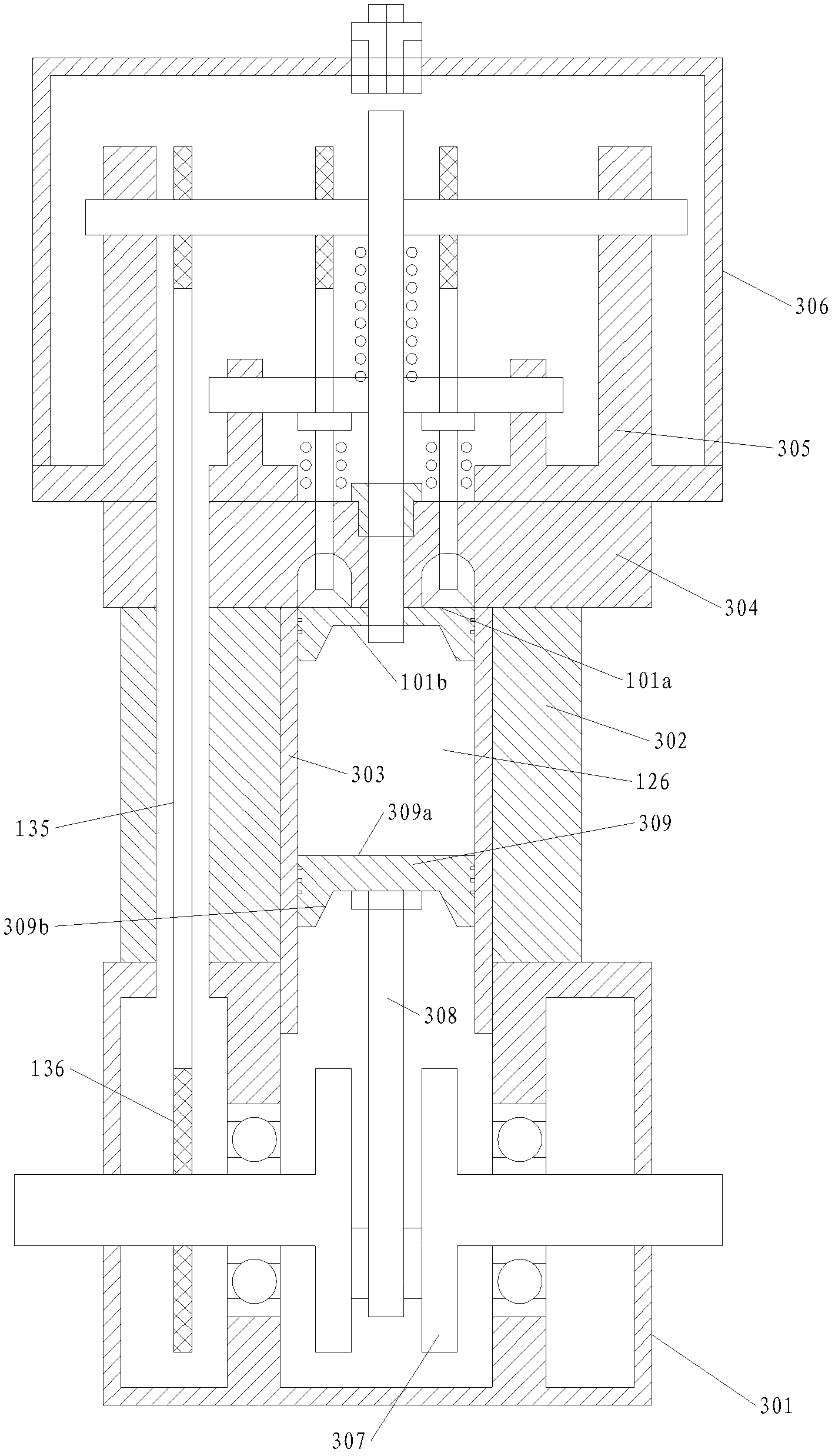
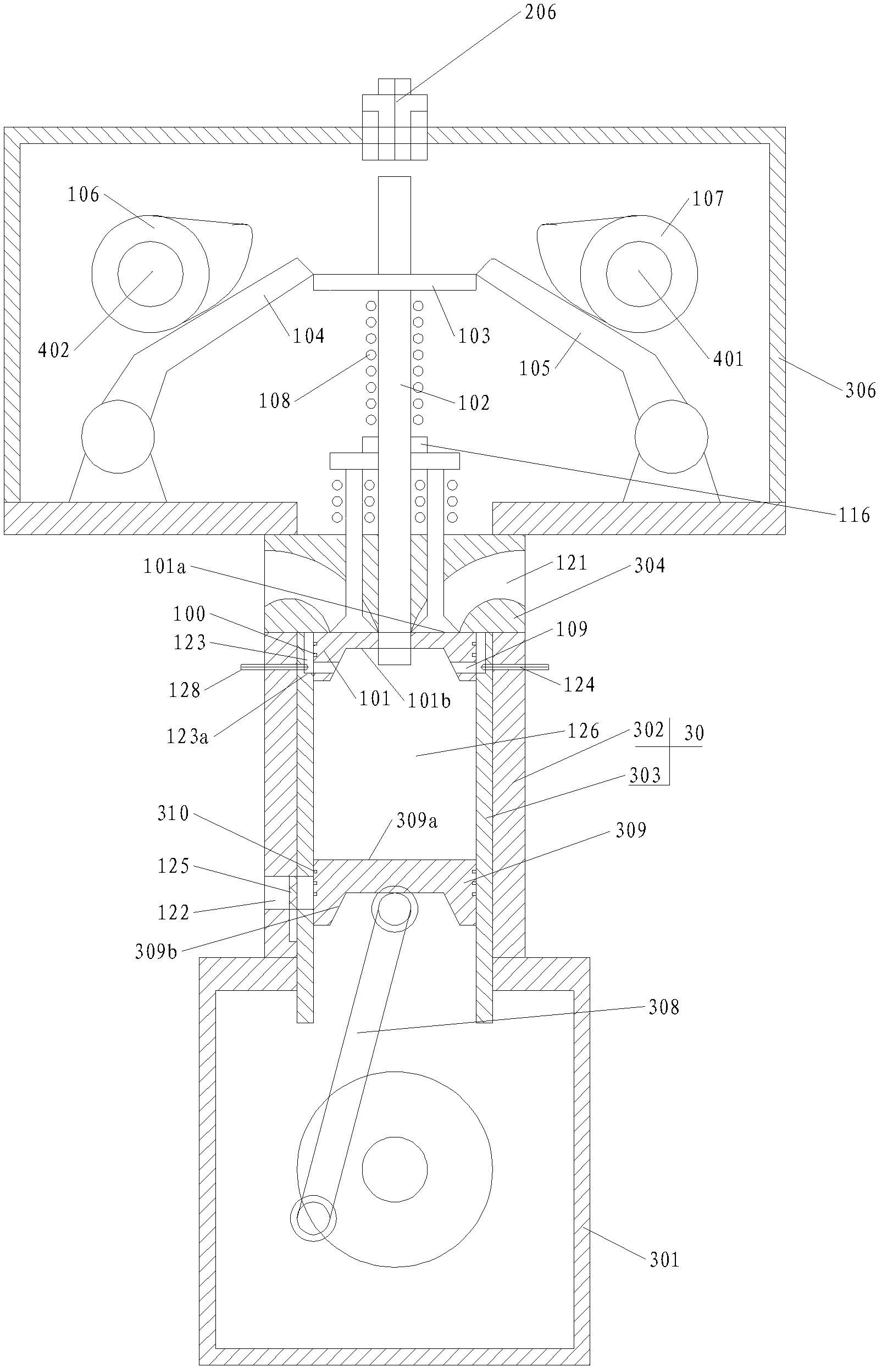
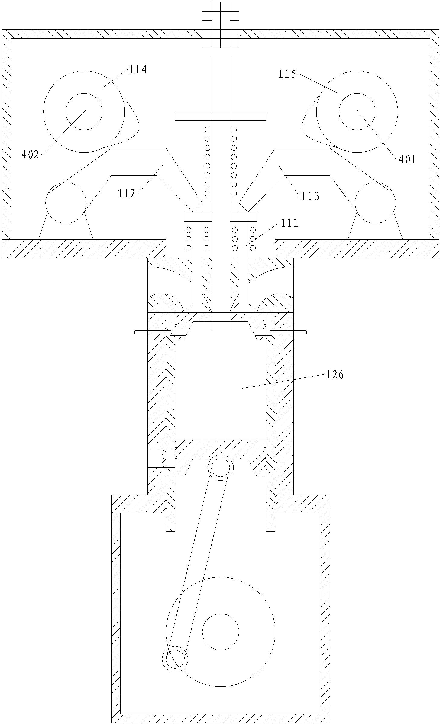
[0072] Such as Figure 1 to Figure 7 and Figure 11 As shown, the single-cylinder three-stroke reciprocating piston engine of the present invention comprises crankcase 301, crankshaft 307 similar to traditional four-stroke engine, crankshaft connecting rod 308, main piston 309, cylinder 30, cylinder head 304 etc. are installed on cylinder heads 304 There is a top cover 306, the main piston 309 is connected with the crankshaft 307 through the crankshaft connecting rod 308, the cylinder head 304 is provided with the intake port 121, the intake valve 111 and the intake valve driving mechanism, and the cylinder 30 is provided with the exhaust port 122 and Exhaust valve 125 and exhaust valve driving mechanism, exhaust valve 125 and exhaust valve driving mechanism can adopt the same or similar mechanism as the prior art, but there is a special exhaust and suction mechanism, according to the three-stroke process described in the present invention Principle works.
[0073] The speci...
Embodiment 2
[0077] Such as Figure 8 As shown, the second embodiment is a three-stroke engine of the present invention with an electric ignition device added on the basis of the first embodiment. Its basic structure is the same as that of the first embodiment, but its auxiliary piston connecting rod 102 is a tubular hollow rod. The ignition device includes an ignition head 201 and an ignition needle 202. The ignition head 201 is arranged on the end of the auxiliary piston connecting rod 102 on the side of the auxiliary piston lower surface 101b, and the ignition needle 202 is installed in the auxiliary piston connecting rod 102 and connected with the auxiliary piston. The rod 102 is insulated, the needle of the ignition needle 202 and the ignition head 201 maintain an ignition gap, and the tail end of the ignition needle 202 is a movable contact 202a, which is connected with the static ignition controller 205 with the movement of the auxiliary piston connecting rod 102. The contact 204a i...
Embodiment 3
[0079] Such as figure 2 and Figure 11 As shown, the engine adopts the direct injection fuel supply mode in the cylinder. The fuel supplied by the fuel supply mechanism of the engine is directly sprayed into the thermal expansion chamber through the fuel nozzle 128. There is no ignition device, and the ignition is achieved by compression ignition. The air guide channel of the engine is composed of Four groups of cylinder air guide passages 123 and piston air guide passages 109 are uniformly distributed relative to the center line of the cylinder 30. The fuel supply mechanism is connected to the two fuel nozzles 128 at the joints of the air guide passage 109 . The fuel nozzle 128 can be fuel injection or gas injection according to different choices of fuel.
PUM
 Abstract
Description
Claims
Application Information
 - R&D
- Intellectual Property
- Life Sciences
- Materials
- Tech Scout
- Unparalleled Data Quality
- Higher Quality Content
- 60% Fewer Hallucinations
Browse by: Latest US Patents, China's latest patents, Technical Efficacy Thesaurus, Application Domain, Technology Topic, Popular Technical Reports.
© 2025 PatSnap. All rights reserved.Legal|Privacy policy|Modern Slavery Act Transparency Statement|Sitemap|About US| Contact US: help@patsnap.com


