High-precision and large-load control system and method of three-axis inertially stabilized platform for airborne remote sensing

An aerial remote sensing and three-axis inertial technology, which is applied in the field of light and high-resolution aerial remote sensing inertial stabilization platform, can solve the problems of inability to solve arbitrary manual control, no manual mode, unfavorable real-time and rapidity of control algorithms, etc.

Inactive Publication Date: 2012-05-02
BEIHANG UNIV
View PDF7 Cites 42 Cited by
  • Summary
  • Abstract
  • Description
  • Claims
  • Application Information

AI Technical Summary

Problems solved by technology

First, the control scheme adopts dual-loop slave control without current loop control, which cannot overcome the impact of power supply voltage and load fluctuation on the system and the problem of excessive current. At the same time, the motor control torque ripple is large and cannot be suppressed; second , the control accuracy of the system is low, which cannot meet the needs of actual aerial survey, and the load capacity is poor, so it cannot be applied to large load occasions; thirdly, the control unit adopts DSP+FPGA solution, and FPGA is only used for encoder signal acquisition and PWM signal generation, not only increases

Method used


Image

  • High-precision and large-load control system and method of three-axis inertially stabilized platform for airborne remote sensing
  • High-precision and large-load control system and method of three-axis inertially stabilized platform for airborne remote sensing
  • High-precision and large-load control system and method of three-axis inertially stabilized platform for airborne remote sensing

Examples


Embodiment Construction

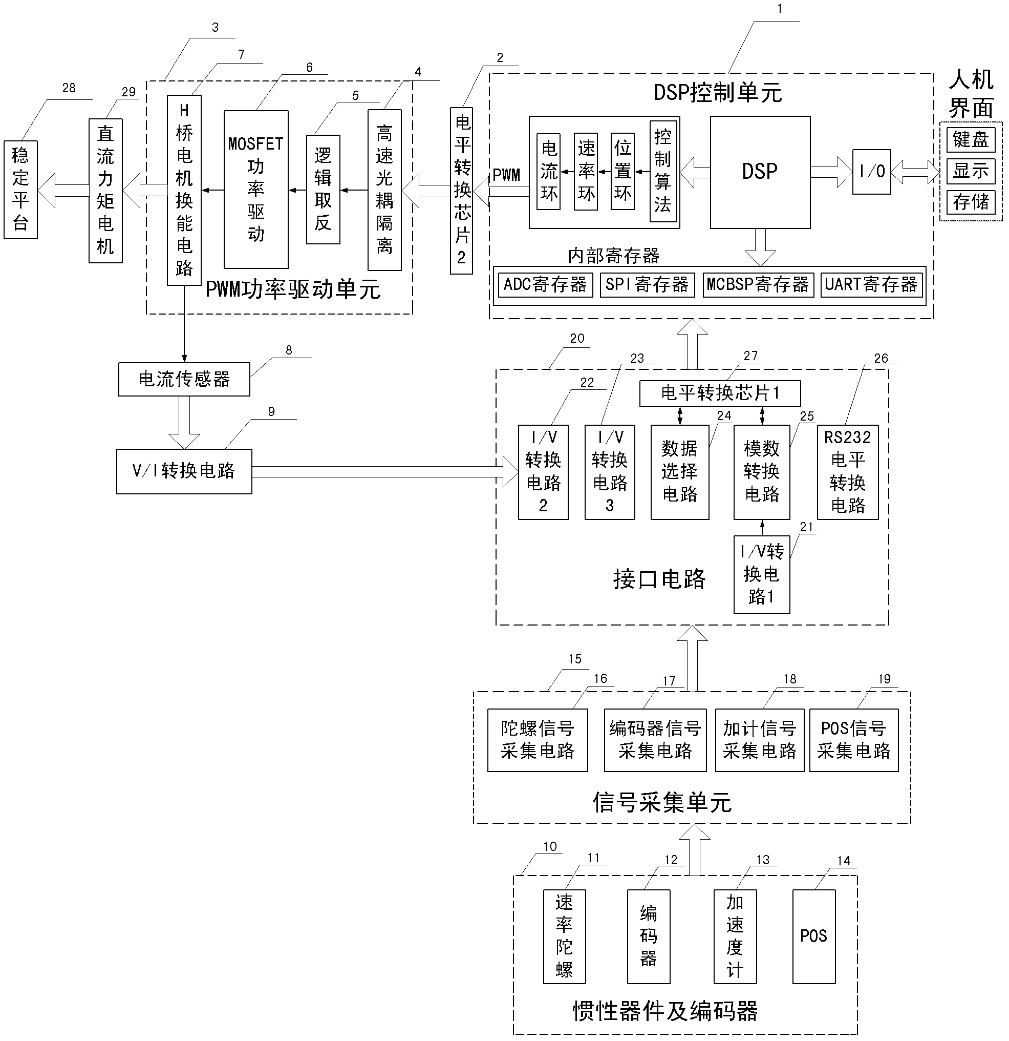
[0046] Such as figure 1 Shown is a structural block diagram of the control system of the present invention, which is mainly composed of a DSP control unit 1, a PWM power drive unit 3, an interface circuit 20, a signal acquisition unit 15, an inertial device, an encoder 10, and the like.

[0047] Among them, the DSP chooses TI's floating-point chip TMS320F28335, which has 32-bit floating-point processing unit, 150MHZ high-speed data processing capability, up to 18 channels of PWM output, 12-bit 16-channel ADC and other characteristics. The register resource is connected with the interface circuit to read the data of each sensor and generate the PWM control value to drive the motor. In the PWM power drive unit 3, the PWM control value is sent to the power drive unit 6 through high-speed optocoupler isolation 4 and logic inversion 5 to increase the output power. Can control.

[0048] Such as figure 1As shown, the current sensor 8 measures the motor coil current, connects to ...


PUM


Abstract

The invention provides a high-precision and large-load control system and method of a three-axis inertially stabilized platform for airborne remote sensing. The system comprises a DSP (digital signal processing) control unit, a PWM (pulse-width modulation) power drive unit, an interface circuit, a signal acquisition unit, an inertial device, an encoder and a direct current (DC) torque motor. The method comprises the following steps: acquiring data such as the attitude angle and angular speed of frameworks relative to an inertial space, coil current and relative corners among the frameworks through the signal acquisition unit; transferring the data into an internal register of the DSP control unit through the interface circuit so that the data is read by the DSP control unit; taking the data as signals to be input into the DSP control unit, and generating PWM controlled quantity by adopting a three-loop (a current loop, a speed loop and a position loop) compound control algorithm; and transferring PWM signals into an energy conversion circuit of an H-bridge DC motor through the power drive unit so as to drive the DC torque motor to change with reference instructions, and finally realizing active control of the inertially stabilized platform. The high-precision and large-load control system and method provided by the invention have the advantages that control precision and loading capability of the system are improved, the control algorithm is completed, and diversity and intellectualization of a platform operating mode are improved.

Description

technical field [0001] The invention relates to a high-precision and large-load aerial remote sensing three-axis inertial stabilization platform control system and control method, belonging to the field of high-resolution aerial earth observation systems, and can be used for three-axis inertial stabilization platforms with large load-carrying ratio and high stability requirements Independent and autonomous control, especially suitable for light and high-resolution aerial remote sensing inertial stabilization platform. Background technique [0002] The inertial stabilization platform is a necessary equipment for realizing high-resolution earth observation. It can effectively isolate the disturbance and non-ideal attitude movement of the flight platform, so that the observation load's boresight pointing and heading always maintain inertial space stability. At present, the representative foreign products are PAV30 and PAV80 of Swiss Leica Company, while domestic related researc...

Claims


Application Information

Patent Timeline
IPC IPC(8): G05D1/08G05D1/10
Inventor 钟麦英李树胜房建成赵岩
Owner BEIHANG UNIV
Why Eureka
Try Eureka