
Residual oil hydrogenation treatment and catalytic cracking combination method

A technology of catalytic cracking and residual oil hydrogenation, which is applied in the field of gasoline production, can solve the problems of increased investment costs, limited naphtha and diesel yield, and reduced total yield, so as to reduce equipment investment and operating energy consumption, and save Eliminate repetitive processing steps and reduce the effect of heat exchange equipment

Active Publication Date: 2012-05-16
CHINA PETROLEUM & CHEM CORP +1
View PDF6 Cites 7 Cited by
  • Summary
  • Abstract
  • Description
  • Claims
  • Application Information

AI Technical Summary

Problems solved by technology

However, in this method, a fractionation system is installed in both the hydrotreating and catalytic cracking processes, which increases the investment cost; due to the heat exchange in the process, the heat energy loss is more; at the same time, both the hydrotreating unit and the catalytic cracking unit have diesel products, relatively speaking , the total yield of gasoline and gas products will decrease
In addition, the residual oil cracking rate of the residual oil hydrotreating unit is low, and the yields of naphtha and diesel oil obtained by fractionating the hydrogenated oil are limited, and the diesel fraction obtained during the residual oil hydrotreating process still cannot meet the high quality requirements. Requirements for Diesel Products

Method used


Image

  • Residual oil hydrogenation treatment and catalytic cracking combination method
  • Residual oil hydrogenation treatment and catalytic cracking combination method
  • Residual oil hydrogenation treatment and catalytic cracking combination method

Examples


Embodiment

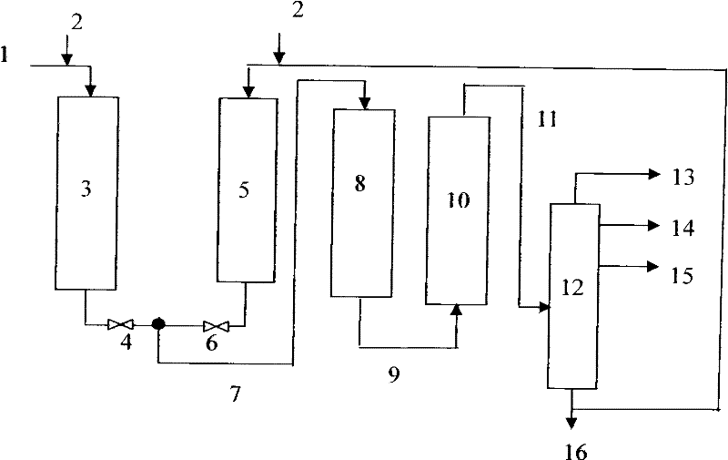
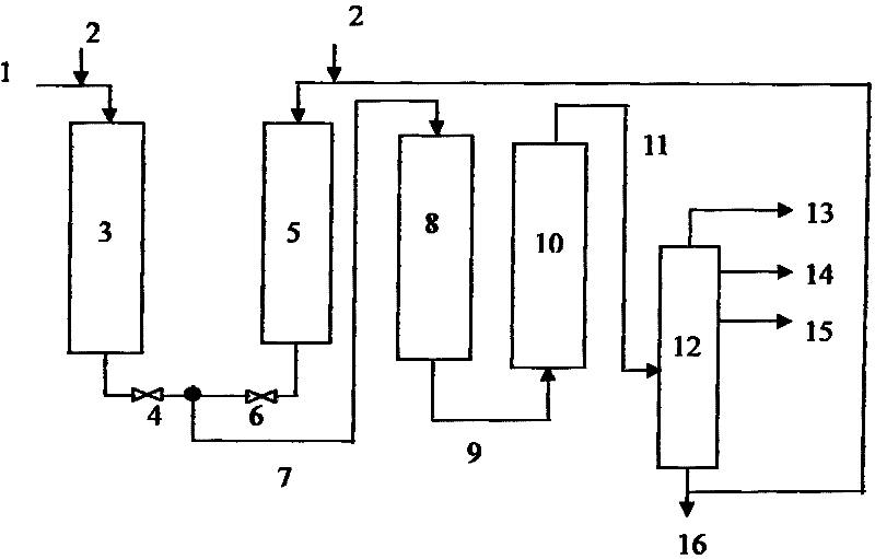
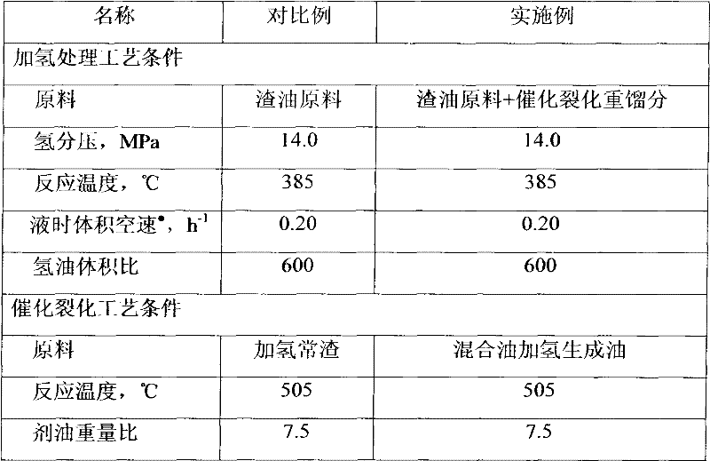
[0035] This embodiment adopts the combined method of residual oil hydrotreating and catalytic cracking provided by the present invention, and the flow chart is shown in figure 1 . Residual oil raw material and catalytic cracking heavy fraction enter different hydrogenation protection reactors respectively, and the hydrogenation streams generated are mixed. The design of the fractionation system is simplified, and only dry gas, liquefied gas and gasoline fractions are fractionated. FCC diesel oil, catalytic cracking cycle oil and catalytic oil slurry are directly used as heavy fractions of catalytic cracking without fractionation, and the heavy fractions of catalytic cracking are recycled after filtering out solid impurities. To hydrogenation protection reactor 5. Table 2, Table 3, Table 4, and Table 6 are the process conditions, product distribution and main product properties respectively.

[0036] The comparison results show that after the catalytic cracking heavy distilla...


PUM


Abstract

The present invention discloses a residual oil hydrogenation treatment and catalytic cracking combination method. According to the method, the residual oil hydrogenation treatment process comprises two hydrogenation protection reactors, wherein the two hydrogenation protection reactors are arranged in parallel connection, the feed material of the first hydrogenation protection reactor is the residual oil raw material, and the feed material of the second hydrogenation protection reactor is the catalytic cracking heavy fraction; the effluents of the two reactors are mixed, and the resulting mixture enters a hydrogenation treatment reaction zone to carry out a hydrogenation reaction; the effluent of the hydrogenation reaction is subjected to gas-liquid separation, wherein the resulting gas phase is circularly adopted for the hydrogenation reaction, and the liquid phase directly enters a catalytic cracking apparatus without fractionation; the effluent of the catalytic cracking reaction is separated to obtain dry gas, liquefied gas, catalytic cracking gasoline, and catalytic cracking heavy fraction after catalytic cracking of the gasoline, wherein the catalytic cracking heavy fraction is adopted as the feed material of the second hydrogenation protection reactor. With the method, the operating period of the residual oil hydrogenation apparatus can be prolonged, the maximum amount of the catalytic cracking gasoline can be produced, and the equipment investment can be saved.

Description

technical field [0001] The invention relates to a method for lightening residual oil, in particular to a process for mainly producing gasoline products by organically combining residual oil hydrotreating and catalytic cracking and using residual oil as a raw material. Background technique [0002] As crude oil becomes heavier and worse, more and more residues need to be processed. The processing of heavy and residual oil is not only to crack it into products with low boiling points, such as naphtha, middle distillate oil and vacuum gas oil, but also to increase their hydrogen-carbon ratio, which requires decarbonization Or hydrogenation method to achieve. The decarbonization process includes coking, solvent deasphalting, heavy oil catalytic cracking, etc.; hydrogenation includes hydrocracking, hydrofining, etc. The hydrogenation method can hydrogenate and convert residual oil, improve the yield of liquid products, and remove heteroatoms therein, and the product quality is ...

Claims


Application Information

Patent Timeline
Patent Type & Authority Applications(China)
IPC IPC(8): C10G69/00
Inventor 刘铁斌李洪广吴锐耿新国翁延博张庆军
Owner CHINA PETROLEUM & CHEM CORP
Learn More