Gas-fired drying part for paper machine

A gas-fired drying section technology, applied to paper machines, dryer sections, papermaking, etc., can solve problems such as large power consumption, low overall efficiency, and pollutant emissions, and achieve reduced energy conversion times, saving infrastructure investment, and Overall weight reduction effect

Active Publication Date: 2015-02-11
HENAN JIANGHE PAPER +1
View PDF11 Cites 2 Cited by
  • Summary
  • Abstract
  • Description
  • Claims
  • Application Information

AI Technical Summary

Problems solved by technology

[0008] 1. Use steam to heat the drying cylinder to dry the paper, the overall efficiency is low, the energy consumption is high, and there is a large amount of carbon dioxide and other pollutants discharged, which is not environmentally friendly
like image 3 , the heat transfer process of the drying section of the traditional paper machine, the boiler converts water into high-pressure steam, the efficiency is about 85%; the high-pressure steam is transported to the drying cylinder through the steam pipe network, the efficiency is about 88%; the drying cylinder then transfers the heat to Paper, its efficiency is about 63%, the overall efficiency of the whole system is only 47%
[0009] 2. The entire drying section has a huge structure and many auxiliary facilities, not only consumes a lot of raw materials, but also consumes a lot of electricity when working
There are many rotating points and bearing positions, the lubrication system is complicated, and the maintenance cost is high
[0010] 3. The entire drying section has a large equipment base and required workshop area, which requires a large investment
[0011] In the past, the transformation of the drying section of the paper machine focused on the utilization of waste heat, and did not fundamentally solve the defects of low overall efficiency and high energy consumption in the drying section of the paper machine

Method used


Image

  • Gas-fired drying part for paper machine
  • Gas-fired drying part for paper machine
  • Gas-fired drying part for paper machine

Examples


Embodiment Construction

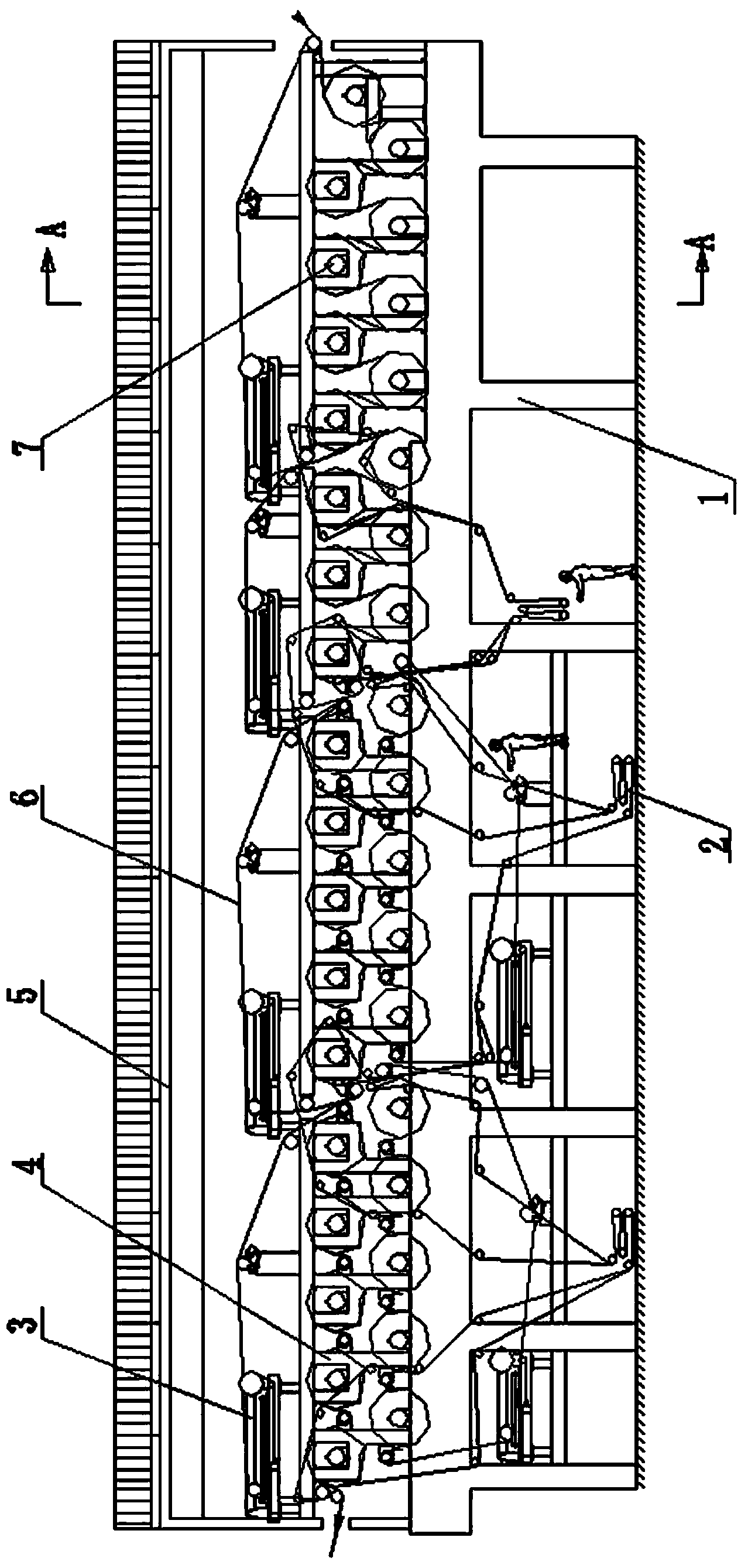
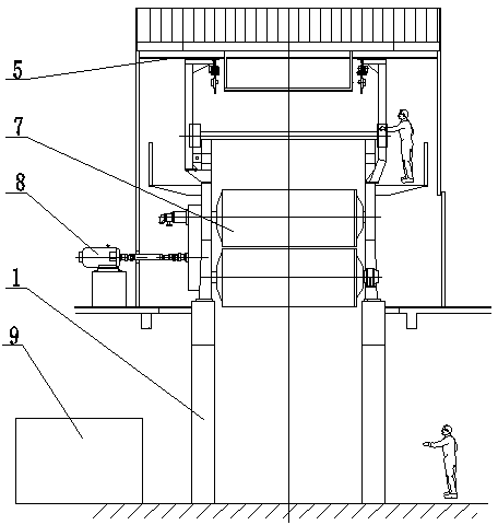
[0027] Such as Figure 4 , Figure 5 and Figure 6 A gas-fired drying section of a paper machine is shown, including an equipment foundation 15, on which a driving roller 11 is arranged, a driving unit 20 drives the driving roller 11, and a driving roller on the paper feeding side is provided with a friction roller to form a friction with the driving roller. The pressure roller 10 of width is provided with endless steel belt 19 on driving roller 11, and driving roller 11 drives endless steel belt 19 circular rotation, is provided with combustion chamber 13 below annular steel belt 19, and combustion chamber 13 is connected with gas pipeline 18 and The air duct 17 is connected, and the wet paper sheets from the pressing unit are pasted on the upper surface of the endless steel belt under the appropriate pressure of the pressing roller, and move forward synchronously with the steel belt. Because the combustion chamber is set under the steel belt, the heat energy after the gas ...


PUM


Abstract

The invention discloses a gas-fired drying part for a paper machine. The gas-fired drying part comprises an equipment foundation, wherein a driving roller is arranged on the equipment foundation; a compression roller which forms a friction pair together with the driving roller is arranged on the driving roller on a paper feeding side; an annular steel strip is arranged on the driving roller; the driving roller is used for driving the annular steel strip to rotate circularly; a combustion chamber is formed on the lower side of the annular steel strip and is communicated with a gas pipeline and an air pipeline; and adjustment pressure reducing valves are arranged on the air pipeline and the gas pipeline. In the drying part for the paper machine, the steel strip of the paper machine is directly heated through heat generated by uniformly mixing natural gas or marsh gas and air according to a certain proportion and fully combusting the natural gas or the marsh gas, and the steep strip transmits the heat to paper, so that a heat energy conversion mode is changed, the conversion frequency of energy is reduced, and a conveying path is shortened; and waste heat of tail gas is smoothly received and utilized by a heat exchanger, purified gas obtained after the tail gas is desulfurized and decarburized returns to the air pipeline to be combusted again, and waste gas is conveyed into a marsh gas tank.

Description

technical field [0001] The invention belongs to equipment in the papermaking industry, and in particular relates to a drying section of a papermaking machine. Background technique [0002] The dry section of a paper machine generally refers to the part between the press unit and the coating unit of the paper machine and the part between the coating unit and the calendering unit. According to its relative position in the whole paper machine production line, it is divided into pre-drying, intermediate drying and post-drying. For large cylinder paper machines, the large diameter dryer also belongs to the drying section of the paper machine. The main function of the drying section of the paper machine is to dehydrate the wet paper web to ensure that the paper sheet reaches the dryness of the finished paper, and at the same time adjust the quantitative consistency of the vertical and horizontal moisture content of the paper sheet to ensure the performance of the paper sheet. ...

Claims


Application Information

Patent Timeline
Patent Type & Authority Patents(China)
IPC IPC(8): D21F5/00
Inventor 姜丰伟刘铸红曾云冯育英李向阳朱平王军清胡年喜张家利郭发旺祝红军邓智莉李长国王法同马晓
Owner HENAN JIANGHE PAPER
Why Eureka
Try Eureka