Method for forming positive electrode of solar cell

A technology for solar cells and front electrodes, applied in circuits, electrical components, photovoltaic power generation, etc., can solve the problems of increasing paste unit consumption, current loss, and increase in component welding debris, so as to improve photoelectric conversion efficiency and improve output electrical performance. , the effect of reducing internal stress

Inactive Publication Date: 2012-05-30
WUXI SUNTECH POWER CO LTD
View PDF5 Cites 10 Cited by
  • Summary
  • Abstract
  • Description
  • Claims
  • Application Information

AI Technical Summary

Problems solved by technology

However, in the traditional screen printing process, one kind of paste is used to print the main grid lines and sub grid lines at the same time. The increase of the height of the busbar not only does not significantly help the electrical performance, but will increase the unit consumption of the paste and increase the cost. At the same time, the height of the busbar is too high, which will also increase the welding debris of the module, which will easily lead to the scrapping of the solar cell.
Therefore, according to the current screen printing technology, it is difficult to further improve the aspect ratio of the auxiliary grid lines of solar cells; and since the main grid lines and auxiliary grid lines use the same paste in the traditional screen printing process, the Both will penetrate the anti-reflection (passivation) film, so that redundant recombination will occur at the busbar position, thereby reducing the electrical performance of the solar cell
[0004] The traditional screen printing process uses a paste to print the main grid and the auxiliary grid at the same time, so the front electrode of the solar cell, especially the auxiliary grid, cannot achieve functional delamination, such as the lower layer of the grid forming ohmic contact with the solar cell For current collection, the upper layer of the grid line only plays a conductive role;
[0005] The traditional screen printing process only prints once, that is, uses one paste to print the main grid line and the sub grid line at the same time, because it is necessary to take into account the influence of the ohmic contact between the front electrode and the silicon, and the sheet resistance of the silicon wafer diffusion can only be controlled. At a low level, this will inevitably cause a loss of current; and if masking or etching windows are used to achieve local re-doping, many additional processes need to be added, the production process is more cumbersome, and the production cost is increased.

Method used


Image

  • Method for forming positive electrode of solar cell
  • Method for forming positive electrode of solar cell
  • Method for forming positive electrode of solar cell

Examples


Embodiment Construction

[0038] The technical solutions in the embodiments of the present invention will be clearly and completely described below in conjunction with the accompanying drawings in the embodiments of the present invention. Obviously, the described embodiments are only some, not all, embodiments of the present invention. Based on the embodiments of the present invention, all other embodiments obtained by persons of ordinary skill in the art without making creative efforts belong to the protection scope of the present invention.

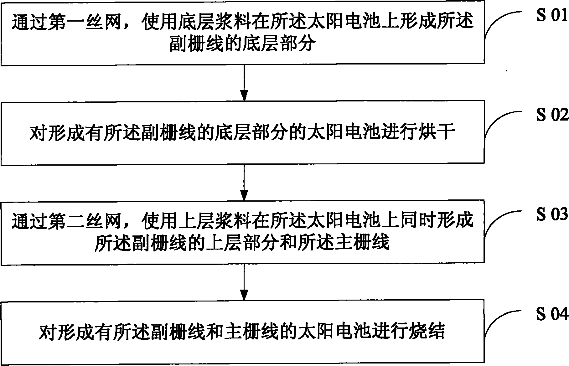
[0039] figure 1 A flowchart of an embodiment of the method for forming the solar cell front electrode provided by the present invention, such as figure 1 As shown, the method for forming the solar cell front electrode of the present embodiment includes:

[0040] S01: forming the bottom layer part of the auxiliary grid line on the solar cell by using the bottom layer paste through the first screen;

[0041] S02: Drying the solar cell at the bottom portion where...


PUM


Abstract

The invention discloses a method for forming a positive electrode of a solar cell, which comprises the step of forming a secondary grid line and a main grid line on the solar cell. The method comprises the following steps of: forming a bottom-layer part of the secondary grid line on the solar cell by using bottom-layer slurry through a first silk net; oven-drying the solar cell formed with the bottom-layer part of the secondary grid line; forming an upper-layer part of the secondary grid line and the main grid line at the same time on the solar cell by using upper-layer slurry through a second silk net; and sintering the solar cell formed with the secondary grid line and the main grid line. By means of the method disclosed by the invention, the height-to-width ratio of the secondary grid line can be increased, the redundant composition will not be produced at the position of the main grid line, the cost of the slurry is effectively reduced, the internal stress produced at an electrode part during assembly production and welding is reduced, and the positive electrode of the solar cell, particularly the electrode at the position of the secondary grid line is enabled to realize functional differentiation. The invention also provides a method for producing the solar cell by using the above method and the solar cell produced by the above method.

Description

technical field [0001] The invention relates to the field of photovoltaic cell manufacturing, in particular to a method for forming solar cell electrodes. Background technique [0002] In recent years, in the development of alternative energy sources, solar cell technology has made great breakthroughs, and its applications have become more and more extensive. In the current photovoltaic industry, due to the mature technology of screen printing technology, simple process and easy control of precision, it is widely used to form the front electrode of solar cells. However, under the current trend of pursuing high-efficiency and low-cost solar cells, screen printing Printing technology has gradually shown its limitations. [0003] In the solar cell manufacturing process, the higher the height of the sub-grid of the solar cell, the lower the resistance of the sub-grid; and the wider the width of the sub-grid, although the resistance can also be reduced, but the effective light-r...

Claims


Application Information

Patent Timeline
Patent Type & Authority Applications(China)
IPC IPC(8): H01L31/18H01L31/05H01L31/0224
CPCH01L31/022425Y02E10/50H01L31/04H01L31/0224H01L31/18
Inventor 张光春汪义川杨健陈如龙薛小兴葛剑黄治国王义华周杰王韬班晓磊王寅
Owner WUXI SUNTECH POWER CO LTD
Why Eureka
Try Eureka