Projection objective structural optimization method for reducing deformation of extreme ultra-violet lithography system

A technology of extreme ultraviolet lithography and optimization method, which is applied in the field of deformation control of extreme ultraviolet lithography objective lens

Active Publication Date: 2012-06-13
BEIJING INSTITUTE OF TECHNOLOGYGY
View PDF4 Cites 7 Cited by
  • Summary
  • Abstract
  • Description
  • Claims
  • Application Information

AI Technical Summary

Problems solved by technology

[0004] In view of this, the problem to be solved by the present invention is to find the optimal thickness and edge width of each mirror of the extreme ultraviolet lithography projection objective lens, thereby reducing the deformation of each mirror without introducing additional devices , to reduce the impact of mirror deformation on the lithography performance of the exposure system

Method used


Image

  • Projection objective structural optimization method for reducing deformation of extreme ultra-violet lithography system
  • Projection objective structural optimization method for reducing deformation of extreme ultra-violet lithography system
  • Projection objective structural optimization method for reducing deformation of extreme ultra-violet lithography system

Examples


Embodiment Construction

[0021] The present invention will be further described in detail below in conjunction with the accompanying drawings and specific examples.

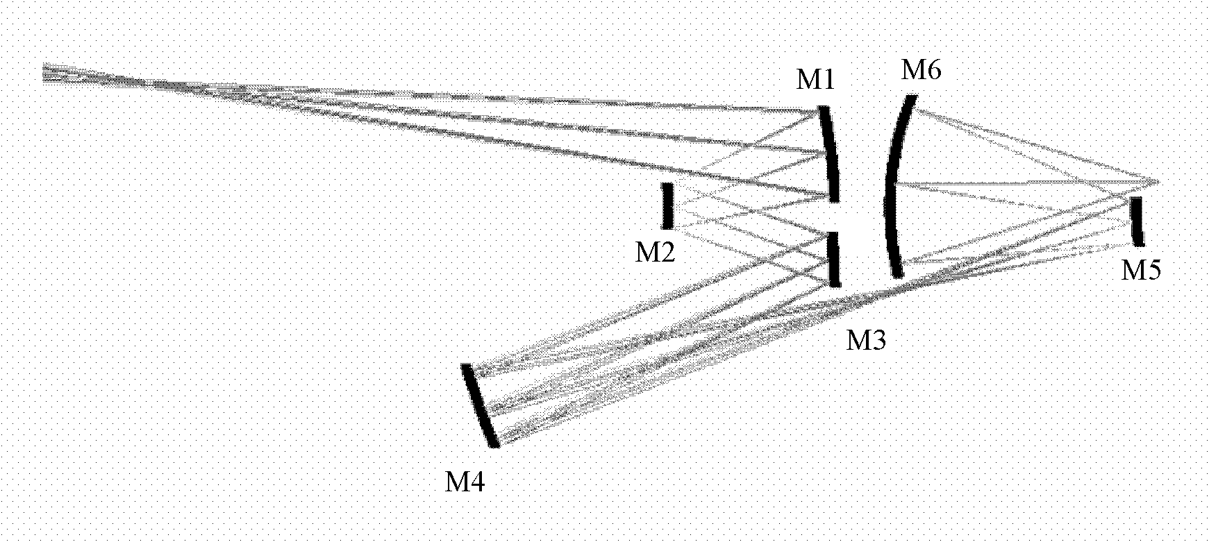
[0022] In order to meet the needs of 22nm industrial extreme ultraviolet lithography, the image square aperture is designed to reach 0.3, the image square field of view width reaches 1.5mm, and the six-sided reflective projection objective lens system, such as figure 1 shown. Name the mirror close to the mask as M1, and name the other mirrors along the optical path, and name the last mirror M6. Under the lithography machine model of typical industrialized EUVL prototype production rate (Table 1), the present invention is illustrated by optimizing the structure of the M2 mirror in the system to control the deformation of the M2 mirror as an example.

[0023]

[0024]

[0025] Table 1 Yield model of industrialized EUVL prototype

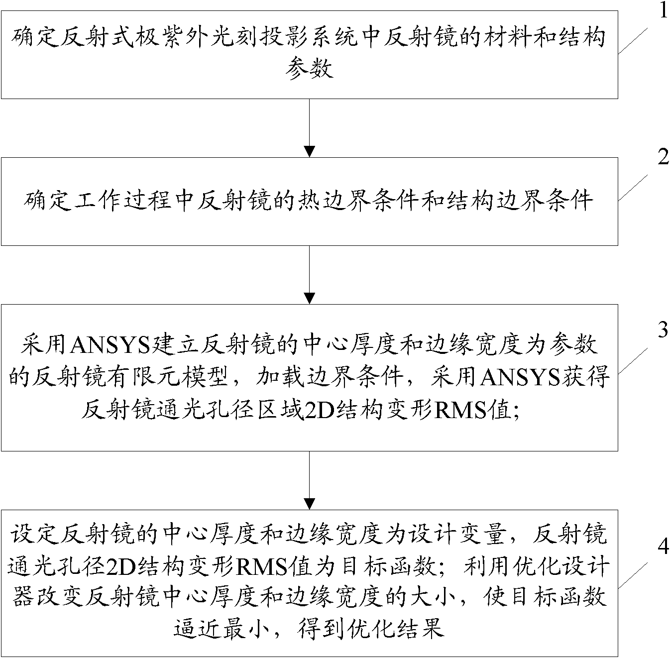
[0026] Such as figure 2 As shown, the flow chart of the projection objective lens structure optimiza...


PUM

PropertyMeasurementUnit
thicknessaaaaaaaaaa
widthaaaaaaaaaa

Abstract

The invention discloses a projection objective structural optimization method for reducing deformation of an extreme ultra-violet lithography system, which adopts finite element simulation software to build a finite element model of a reflector to be optimized with the center thickness and the border width of the reflector as parameters. Then thermal boundary conditions and structural boundary conditions of the reflector are loaded, the finite element simulation software is used for obtaining structural distortion of each panel point of the reflector, and therefore, a two-dimensional (2D) structural distortion root mean square (RMS) value of a clear aperture area of the reflector is calculated. The center thickness and the border width of the reflector are set to be design variables in the finite element simulation software, the 2D structural distortion RMS value of the clear aperture of the reflector is set to be a target function, the center thickness and the border width of the reflector are changed, and the target function is approximately smallest. The center thickness and the border width of the reflector corresponding to the minimum value of the target function are considered to be optimizing results. The projection objective structural optimization method can reduce deformation of each face of the reflector and reduce influences of deformation of the reflector on photoetching performance of an exposure system without introducing additional-adding devices.

Description

technical field [0001] The invention relates to the technical field of deformation control of an extreme ultraviolet lithography objective lens, and specifically designs a projection objective lens structure optimization method for reducing deformation of an extreme ultraviolet lithography projection system. Background technique [0002] The status of extreme ultraviolet lithography (EUVL) as the mainstream technology of 22nm-14nm technology node very large scale integrated circuit lithography process is increasingly emerging. In order to obtain a resolution close to the diffraction limit in EUVL, the root mean square (RMS) value of the total wave aberration of the projection objective lens should be less than 1nm (λ / 14, λ=13.5nm). For a six-mirror system, this requires that the RMS value of each mirror surface deformation is less than 0.2nm ( n=6). However, in the EUV band, almost all known optical materials have strong absorption, and the traditional refractive optical ...

Claims


Application Information

Patent Timeline
Patent Type & Authority Applications(China)
IPC IPC(8): G02B27/00G03F7/20G06F17/50
Inventor 李艳秋杨光华刘菲
Owner BEIJING INSTITUTE OF TECHNOLOGYGY
Why Eureka
Try Eureka