
Shell for packaging microwave assembly and laser sealing method of shell

A technology for microwave components and shells, which is applied in the field of microwave component packaging and its laser sealing, which can solve problems such as restrictions, component risks, and temperature rise inside the package, and achieve automatic operation, no flux pollution, and soldering depth controllable effect

Inactive Publication Date: 2012-06-13
WUXI HUACE ELECTRONICS SYST
View PDF2 Cites 17 Cited by
  • Summary
  • Abstract
  • Description
  • Claims
  • Application Information

AI Technical Summary

Problems solved by technology

Although using a heated platform lid is slightly faster, the metal package acts as a heat sink, raising the temperature inside the package, unless the ambient pressure outside the package can increase at the same time as the pressure inside due to package heating. , due to the difference in pressure inside and outside the package will cause the gas to pass through the weld, that is, the leakage of the air hole
At the same time, due to the rise of the internal temperature of the package, it also brings risks to the components inside the package.
Moreover, traditional soldering materials have disadvantages such as easy oxidation, poor fatigue resistance, flux contamination, and poor reworkability, which limit the use of low-temperature soldering materials.

Method used

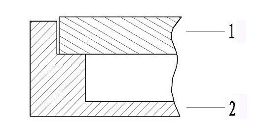
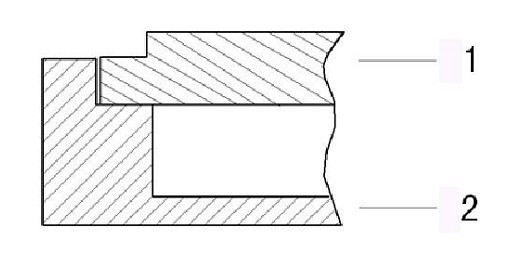
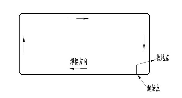

Image

  • Shell for packaging microwave assembly and laser sealing method of shell
  • Shell for packaging microwave assembly and laser sealing method of shell
  • Shell for packaging microwave assembly and laser sealing method of shell

Examples


Embodiment Construction

[0020] In order to deepen the understanding of the present invention, the present invention will be further described below in conjunction with the embodiments and accompanying drawings. The embodiments are only used to explain the present invention and do not constitute a limitation to the protection scope of the present invention.

[0021] Such as Figure 1 to Figure 3 As shown, the casing for microwave component packaging of the present invention includes an aluminum-silicon alloy casing 2 and a 4047 aluminum alloy cover plate 1 with a thickness of 1.5 mm, and the aluminum-silicon alloy casing 2 is docked with the 4047 aluminum alloy cover plate 1 .

[0022] The above-mentioned laser sealing method for the casing used for packaging microwave components comprises the following steps:

[0023] a. Cleaning: use acetone to clean the aluminum-silicon alloy shell 2 and the 4047 aluminum alloy cover plate 1;

[0024] b. Joint assembly: use tooling to connect the aluminum-silicon ...


PUM

PropertyMeasurementUnit
thicknessaaaaaaaaaa

Abstract

The invention relates to a shell for packaging a microwave assembly and a laser sealing method of the shell. The shell for packaging the microwave assembly comprises an aluminum silicon alloy shell and a 4047 aluminum alloy cover plate, wherein the aluminum silicon alloy shell is abutted with the 4047 aluminum alloy cover plate. The laser sealing method comprises the following steps of: cleaning the aluminum silicon alloy shell and the 4047 aluminum alloy cover plate by using acetone, then abutting the aluminum silicon alloy shell with the 4047 aluminum alloy cover plate by using a tool, then fixing the aluminum silicon alloy shell and the 4047 aluminum alloy cover plate by using an Nd:YAG laser, and continuously integrally welding the shell by using the Nd-YAG laser, welding from the bottom of the aluminum silicon alloy shell until reaching the surface of the 4047 aluminum alloy cover plate, wherein the two welding processes are carried out in a nitrogen protective gas. The invention is used for carrying out sealing by using the laser, is easy to realize, has good sealing property and controllable welding depth, can be used for repaired for two times, has little thermal impact to a substrate and a chip because local heating is adopted in the welding process, can realize automatic operation, and has no soldering flux pollution and high reliability.

Description

technical field [0001] The invention relates to a casing for packaging microwave components and a laser sealing method thereof. Background technique [0002] Due to the advantages of small size, light weight and long service life, microwave components have attracted much attention. Kovar alloy, the traditional packaging material for microwave components, is limited in its wide application due to its low thermal conductivity, high resistivity, and high density. Aluminum-silicon alloy materials not only have high strength, but also have good thermal conductivity, low thermal expansion coefficient, and low density, and have good thermal matching with ceramic substrates and gallium arsenide chips or silicon chips. These properties make aluminum-silicon alloy one of the preferred housing materials for microwave component packaging on ceramic substrates. [0003] Aluminum-silicon alloy is usually used as the shell material. First, the surface of the aluminum-silicon alloy is pla...

Claims


Application Information

Patent Timeline
Patent Type & Authority Applications(China)
IPC IPC(8): H01J23/12H01J9/24B23K26/20B23K26/24
Inventor 施冬跃
Owner WUXI HUACE ELECTRONICS SYST
Learn More