Denitration process and denitration apparatus for cement kiln flue gas

A cement kiln and flue gas technology, applied in gas treatment, membrane technology, dispersed particle separation, etc., can solve the problems of shortening the service life of the catalyst, increasing the operating cost, and deactivating the catalyst, so as to reduce the investment and operation cost, save the occupation land area, the effect of reducing the ammonia escape rate

Active Publication Date: 2012-06-27
ZHEJIANG TIANLAN ENVIRONMENTAL PROTECTION TECH
View PDF5 Cites 30 Cited by
  • Summary
  • Abstract
  • Description
  • Claims
  • Application Information

AI Technical Summary

Problems solved by technology

Although the denitrification efficiency of the above patent application is very high, the SCR denitrification section is still a high temperature section, which can only be applied to coal-fired boilers, and the gas components to be processed contain more SO 2 , will lead to deactivation of the catalyst, shorten the service life of the catalyst, and greatly increase the operating cost; this patent is not applicable to the secondary denitrification after the cement kiln humidification tower or dust removal system at low temperature

Method used


Image

  • Denitration process and denitration apparatus for cement kiln flue gas
  • Denitration process and denitration apparatus for cement kiln flue gas
  • Denitration process and denitration apparatus for cement kiln flue gas

Examples


Embodiment 1

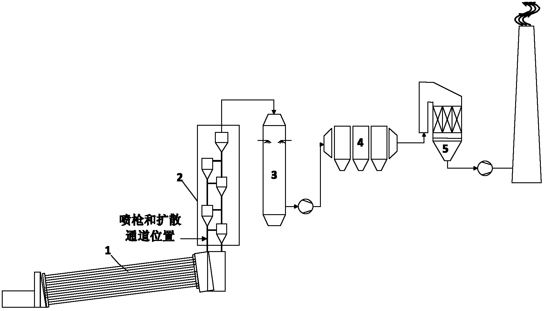
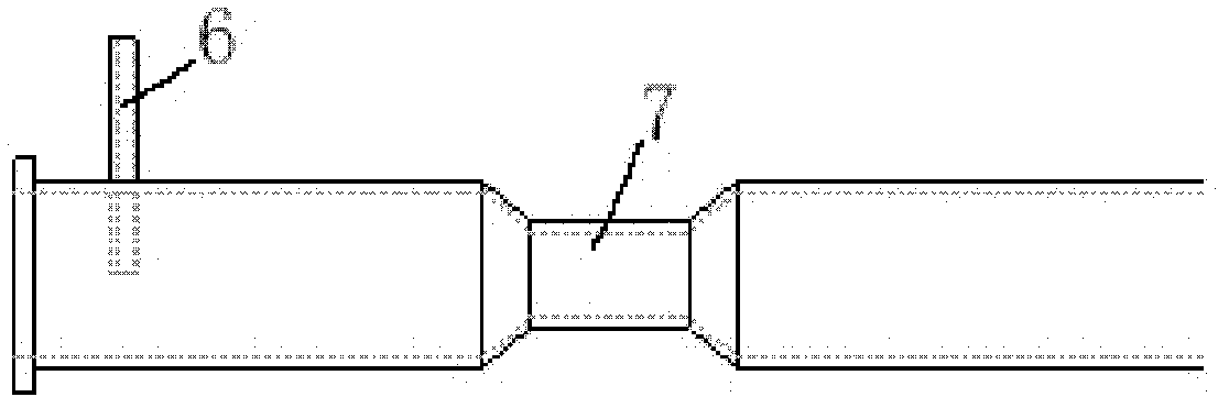
[0024] Such as figure 1 The shown cement kiln flue gas denitrification device includes a cement decomposition kiln 1, a waste heat boiler 2, a humidifying tower 3, a dust collector 4 and an SCR reactor 5 connected in sequence, and the SCR reactor is a honeycomb reactor. In the temperature range of 750℃~1100℃, the concentration of nitrogen oxides is 600mg / m 3 A spray gun is arranged at half of the tail flue of the cement decomposition kiln 1, and a contraction diffusion channel is arranged behind the spray gun (such as figure 2 As shown), the reducing agent is injected according to the molar ratio of the injected amount of the reducing agent to the molar ratio of nitrogen oxides in the flue gas of 2.0:1, and the injection speed is 15m / s. The reducing agent is mixed with the flue gas in the flue, and has a selective non-catalytic reaction with nitrogen oxides, and most of the NO X reduced to N 2 .

[0025] The SCR reactor is arranged at the tail of the dust collector 4 with...

Embodiment 2

[0027] A cement kiln flue gas denitrification device, comprising a cement decomposition kiln 1, a waste heat boiler 2, a humidification tower 3, a dust collector 4 and an SCR reactor 5. The difference from Example 1 is that the SCR reactor 5 is installed Between the humidification tower 3 and the dust collector 4.

[0028] In the temperature range of 750℃~1100℃, the concentration of nitrogen oxides is 600mg / m 3 The spray gun 6 is arranged at one-half of the tail flue of the cement decomposition kiln 1, and the reducing agent is injected according to the injection amount of the reducing agent and the molar ratio of nitrogen oxides in the flue gas is 2.4:1, and the injection speed is is 15m / s. The reducing agent is mixed with the flue gas in the flue, and has a selective non-catalytic reaction with nitrogen oxides, and most of the NO X reduced to N 2 .

[0029] The SCR reactor 5 is arranged at the tail of the humidification tower 3 with a temperature of about 160°C. It is lo...

Embodiment 3

[0031] A cement kiln flue gas denitrification device, the equipment layout is the same as in Example 2, the temperature range is 750°C to 1100°C, and the nitrogen oxide concentration is 550mg / m 3 A spray gun is arranged at half of the tail flue of the cement decomposition kiln 1, and the reducing agent is injected according to the molar ratio of the injected amount of the reducing agent to the nitrogen oxide in the flue gas being 2.0:1. The reducing agent is mixed with the flue gas in the flue, and has a selective non-catalytic reaction with nitrogen oxides, and most of the NO X reduced to N 2 .

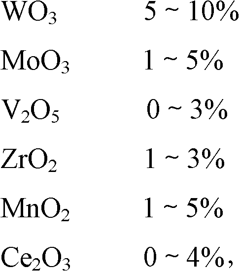
[0032] The SCR reactor 5 is arranged at the tail of the humidification tower 3 with a temperature of about 160°C. It is loaded with a honeycomb-shaped, medium-low temperature and high-activity catalyst that is resistant to alkaline earth alkali metals. Its active components mainly include: 8.5% WO 3 , 3.6% MoO 3 , 2.9% V 2 o 5 , 2.8% ZrO 2 , 4.2% MnO 2 , 3.3% Ce 2 o 3 , the ...


PUM


Abstract

The invention discloses a denitration process for cement kiln flue gas. According to the process, liquefied ammonia, ammonia water or urea is used as a reducing agent and is injected into cement decomposition kiln flue gas in a temperature range of 750 to 1100 DEG C by a spray gun for a selective uncatalyzed reaction, and then the reducing agent and unreacted nitrogen oxides in the flue gas pass through an SCR reaction system installed behind a humidifying tower and a deduster together and undergo a selective uncatalyzed reaction on the surface of a specially-produced low temperature catalyst so as to realize secondary denitration. The invention also discloses a denitration apparatus used for realizing the denitration process. According to the invention, through installation of an SCR denitration system at the tail of a system, the escape rate of ammonia in an SNCR system is reduced; meanwhile, through former SNCR preliminary denitration, the volume of an SCR reactor and usage amount of the catalyst are reduced, thereby reducing cost of one-shot investment for the denitration system and improving denitration efficiency of the system. The denitration process and denitration apparatus provided in the invention are applicable to removal of nitrogen oxides in cement kiln flue gas and have wide market and application prospects.

Description

technical field [0001] The invention relates to a technology for controlling pollutants discharged from cement kilns, in particular to a cement kiln flue gas denitrification process and a denitrification device for efficiently removing nitrogen oxides under specific conditions. Background technique [0002] Nitrogen oxides, as one of the main air pollutants, are the targets of the country's strict emission control after sulfur dioxide. At present, the total amount of nitrogen oxide emissions in my country is about 16.245 million tons, of which about 1.6 million tons are emitted from cement kilns, accounting for about one-tenth of the total emissions. The most widely used flue gas denitrification technologies are SCR technology and SNCR technology. The denitrification efficiency of SCR technology can reach more than 95%. However, due to its large investment, complex system, short catalyst life, and high operating costs, it is not suitable for low temperature and low sulfur c...

Claims


Application Information

Patent Timeline
Patent Type & Authority Applications(China)
IPC IPC(8): B01D53/75B01D53/90B01D53/56
CPCB01D53/56B01D53/8625B01D2251/2062B01D2258/0233
Inventor 李世远王岳军莫建松吴忠标
Owner ZHEJIANG TIANLAN ENVIRONMENTAL PROTECTION TECH
Why Eureka
Try Eureka