
Improved integrated sewage treatment device

A sewage treatment device and improved technology, applied in biological water/sewage treatment, water/sludge/sewage treatment, aerobic and anaerobic process treatment, etc. Effect

Inactive Publication Date: 2012-07-11
CHINESE RES ACAD OF ENVIRONMENTAL SCI
View PDF4 Cites 15 Cited by
  • Summary
  • Abstract
  • Description
  • Claims
  • Application Information

AI Technical Summary

Problems solved by technology

In recent years, many scholars have done a lot of related research on the partial nitrosation-anammox combined process ([Zuo Jian'e, Meng Aihong, a new biological denitrification process-SHARON-ANAMMOX combined process[J], Water supply and drainage, 2001, 27(10): 22-27], [Wang Huizhen, Wu Junqi, Gao Zhiming, new process of semi-nitrification-ANAMMOX denitrification [J], Environmental Engineering, 2001, 19(5): 7- 9], [van Dongen, U., Jetten, M., Van Loosdrecht, M. (2001): The SHARON-ANAMMOX process for treatment of ammonium rich wastewater. Wat. Sci. Technol., 44, 153-160], [van Hulle, S.W.H., Van Den Broeck, S., Maertens, J., Villez, K., Donckels, B.M.R., Schelstraete, G., Volcke, E.I.P., Vanrolleghem, P.A. (2005): Construction, start-up and operation of a continuously aerated laboratory-scale SHARON reactor in view of coupling with an Anammox reactor, Wat.SA., 31, 327-334]), but the sewage treated by this process still contains some nitrate nitrogen and nitrite Salt nitrogen, causing the inorganic nitrogen removal rate of the process to stay at 75±10%, so in order to achieve a higher nitrogen removal rate, denitrification treatment of nitrate nitrogen and nitrite nitrogen in the effluent is necessary

Method used


Image

  • Improved integrated sewage treatment device
  • Improved integrated sewage treatment device

Examples


Embodiment Construction

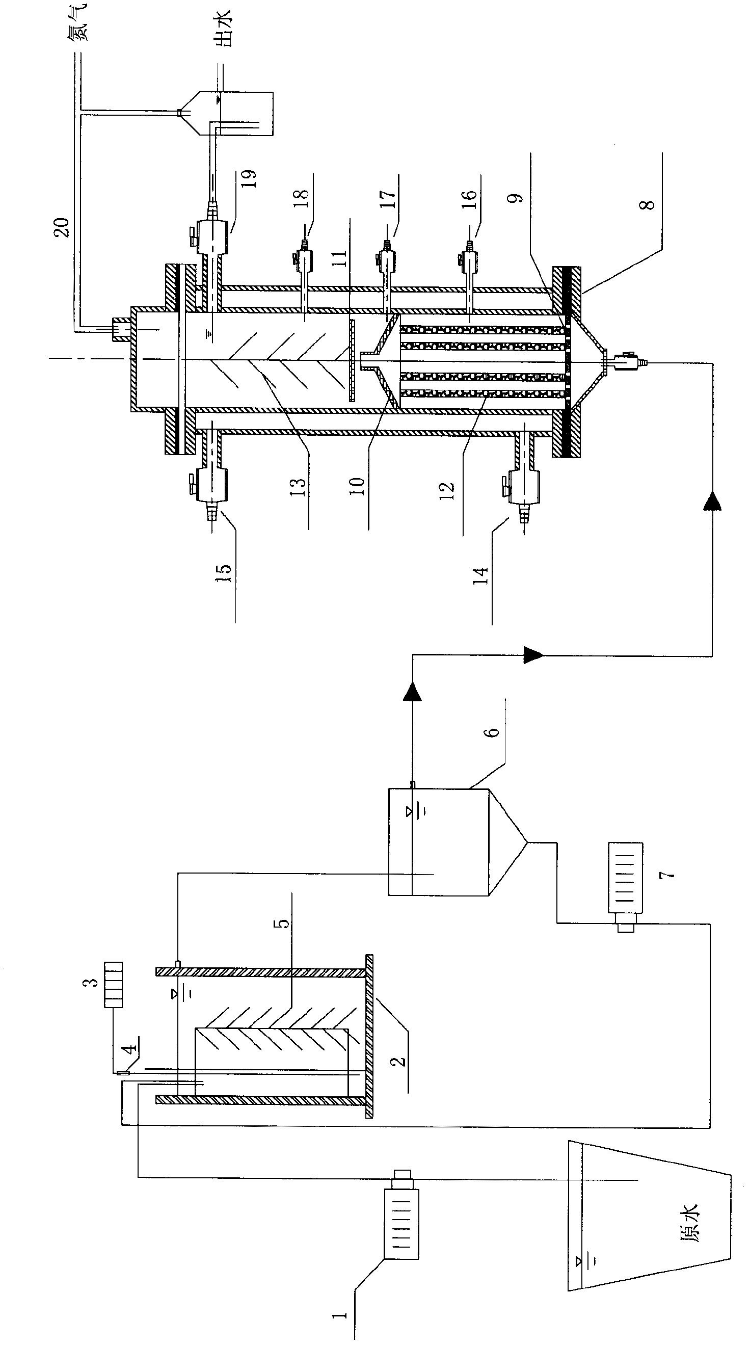
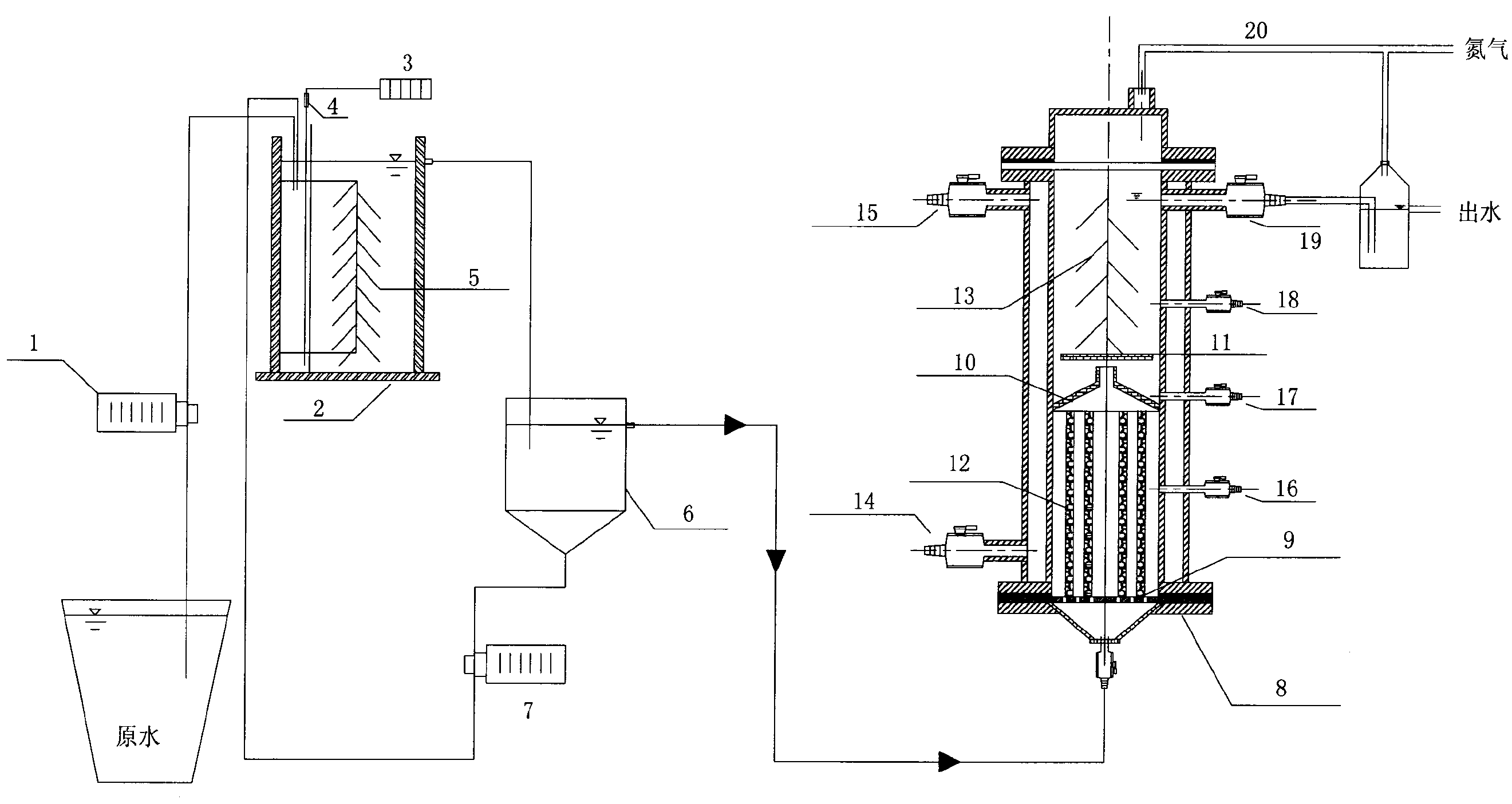
[0029] The sewage treatment device provided by the present invention mainly includes two parts, the first part is a swimming bed reactor for partial nitrosation (PN), and the second part is a reactor for anaerobic ammonium oxidation (Anammox) and denitrification (DN). upflow reactor.

[0030] The swimming bed reactor of the first part includes;

[0031] Inside the swimming bed reactor is a new type of sludge-attached filler biofringe; outside the swimming bed reactor is connected an aeration pump and an air flow meter to aerate the raw water in the swimming bed reactor; inside the swimming bed reactor is also Heating rods can be installed to control the temperature of raw water treatment in the swimming bed reactor at about 25°C-28°C;

[0032] The raw water is connected to the swimming bed reactor with a water inlet pump,

[0033] A sedimentation tank is used to receive the supernatant of the swimming bed reactor, and return the remaining sludge in the sedimentation tank to ...


PUM


Abstract

The invention discloses an improved integrated sewage treatment device. A settling tank is connected with a water outlet at the upper part of a swimming bed reactor; the bottom of the settling tank is connected with the interior of the swimming bed reactor through a circulating pump; the swimming bed reactor is connected with an aeration pump; biofringe filler is filled in the swimming bed reactor; an up-flow type reactor adopts a cylindrical double-layer structure; the top of a reaction layer is at closed state, and an air outlet is arranged at the top of the reaction layer; a water distributor is arranged at the bottom of the reaction layer; a circular baffle plate is arranged above the water distributor; the reaction layer is divided into an upper layer reaction chamber and a lower layer reaction chamber by the circular baffle plate; a three-phase separator is arranged between the water distributor and the circular baffle; biofringe filler is filled in the upper layer reaction chamber; polyethylene sponge filler is vertically distributed in the lower layer reaction chamber; and a water inlet is arranged at the bottom of the up-flow type reactor, which is connected with a water outlet at the upper part of the settling tank. According to the improved integrated sewage treatment device, the technologies of anaerobic ammonium oxidation and denitrification are conducted in a reactor, therefore, the space is saved, and the nitrogen removal efficiency is improved.

Description

technical field [0001] The invention relates to a sewage treatment device, in particular to an improved integrated (PN-Anammox-DN) sewage treatment device. Background technique [0002] The situation of environmental pollution and climate change is severe, and ammonia nitrogen pollution has gradually attracted great attention from all sides. The "Twelfth Five-Year Plan" of the Ministry of Environmental Protection clearly puts forward a plan to control ammonia nitrogen emissions, and its total emissions will be reduced by 10% compared with 2010. Nitrogen pollution in water is becoming more and more serious. At present, ammonia nitrogen in sewage is widely used in traditional nitrification-denitrification process. High energy consumption (nitrification aeration) and heterotrophic denitrification requires additional organic carbon source and dosing of alkali to neutralize the acid produced in the nitrification process, which greatly increases investment and operating costs. T...

Claims


Application Information

Patent Timeline
IPC IPC(8): C02F3/30C02F3/34
Inventor 霍守亮张莉席北斗张靖天苏婧
Owner CHINESE RES ACAD OF ENVIRONMENTAL SCI
Learn More