
Modeling method for equivalent circuit of high-sensitivity quantum effect photodetector

A photodetector and equivalent circuit model technology, applied in circuit design and electronic fields, can solve the problems of complicated programming, inability to reflect, difficult to read circuit design, etc., to achieve flexible modification, simple circuit modeling program, Efficient effect

Active Publication Date: 2012-07-11
EAST CHINA NORMAL UNIVERSITY
View PDF6 Cites 7 Cited by
  • Summary
  • Abstract
  • Description
  • Claims
  • Application Information

AI Technical Summary

Problems solved by technology

Due to the excessive number of physical characteristic parameters inside the photodetector device and the approximate expressions obtained based on various assumptions when solving a large number of physical characteristic equations, the accuracy of the equivalent circuit model will be greatly affected. Difficulties in circuit design
Moreover, during the solution process, due to the complex structure of the photodetector and the various material parameters used, it will also complicate the programming in the modeling process.
[0004] In the patent number: ZL 200910047116.X "A Design Method for Photodetector Readout Circuit", a simple and practical equivalent circuit modeling method is proposed, which is based on the I-V and C-V electrical characteristics of the device. The limitation of this modeling method is that it cannot reflect the I-V and C-V characteristics of photodetectors under different irradiated light powers, and the I-V and C-V characteristics of photodetectors will change with the irradiated light power
Therefore, the current modeling method for the equivalent circuit of the photodetector has certain limitations.

Method used


Image

  • Modeling method for equivalent circuit of high-sensitivity quantum effect photodetector
  • Modeling method for equivalent circuit of high-sensitivity quantum effect photodetector
  • Modeling method for equivalent circuit of high-sensitivity quantum effect photodetector

Examples


Embodiment Construction

[0029] Below with a kind of embodiment that the quantum effect photodetector with a kind of sensitivity is higher under the light power irradiation below 5nW equivalent circuit modeling, the present invention will be further described, and its specific modeling steps are as follows:

[0030] (1) Test of characteristic parameters of photodetectors

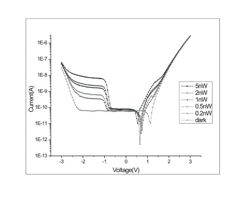
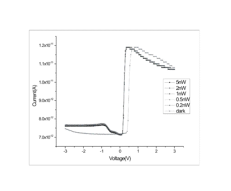
[0031] Based on the photoelectric test platform, using the Kelthley 4200-SCS semiconductor characteristic analyzer and the He-Ne laser with a wavelength of 633nm, the quantum dot-quantum well photodetector is tested under the conditions of no light (dark current) and irradiated light power of 0.2 nW and 0.5 nW, respectively. nW, 1 nW, 2 nW and 5 nW I-V and C-V electrical characteristic parameters, and make a photodetector electrical characteristic curve cluster.

[0032] See attached figure 1 , it can be seen that the quantum effect photodetector of this low-light test system has very low noise (pA) at low temperature (120K), and h...


PUM


Abstract

The invention discloses a modeling method for an equivalent circuit of a high-sensitivity quantum effect photodetector. The modeling method is characterized in that a quantum dot-quantum well photodetector is subjected to electrical characteristic tests under the conditions of different radiation powers and device biases, and an equivalent circuit model is established by using a 'VerilogA' language, and is verified by circuit simulation software, so that a photodetector model capable of accurately reflecting the characteristics of devices with different structures is provided for the design of a readout circuit. Compared with the prior art, the modeling method disclosed by the invention has the advantages that: the modeling method is simple in modeling procedure, flexible in modification and high in efficiency; settings of different corresponding optical power and device bias parameters can be conveniently modified; and the different optical powers and the different device biases can be realized by directly inputting specific data in corresponding preset optical power and device bias parameters in the attributes of the equivalent circuit model.

Description

technical field [0001] The invention relates to the technical field of electronics and circuit design, in particular to a modeling method for an equivalent circuit of a high-sensitivity quantum effect photodetector. Background technique [0002] Photodetectors play the role of converting received light signals into electrical signals. In recent years, with the development of quantum well, quantum dot physics and material technology, quantum effect photodetectors have emerged as the times require. Quantum-effect photodetectors have the advantages of small dark current, high sensitivity, large dynamic range, and high photoelectric conversion efficiency under low-light irradiation. They are widely used in medical, biomolecular science, and environmental monitoring. The main function of the readout circuit in the photodetection system is to preprocess the weak signal of the detector and provide an interface between the signal processing stages. In the design of the readout circ...

Claims


Application Information

Patent Timeline
IPC IPC(8): G01J1/44G06F17/50
Inventor 郭方敏王明甲宋东东朱自强
Owner EAST CHINA NORMAL UNIVERSITY
Learn More