
Charging-discharging system for V2G bilateral power conversion electric automobile and control method thereof

A technology of electric vehicles and control methods, applied to electric vehicles, converting AC power input to DC power output, and converting DC power input to DC power output, etc., can solve problems such as uncontrollability, consumption of non-ferrous metals, and large losses

Active Publication Date: 2012-07-11
NORTH CHINA ELECTRIC POWER UNIV (BAODING)
View PDF3 Cites 69 Cited by
  • Summary
  • Abstract
  • Description
  • Claims
  • Application Information

AI Technical Summary

Problems solved by technology

[0003] The traditional charger uses silicon controlled rectifier bridge rectifier circuit to form the charging main circuit to realize the battery charging function, but the disadvantage is that the power conversion adopts the power frequency phase control method, which leads to serious distortion of the AC current waveform and large harmonic components; low power factor, And it is uncontrollable; moreover, the use of power frequency transformers to transform voltage and electrical isolation results in large losses, resulting in low energy conversion efficiency of the whole machine, and consumes a large amount of non-ferrous metals, resulting in high cost
[0007] However, further analysis of the circuit topology of electric vehicle chargers shows that ordinary electric vehicle chargers do not yet have the ability to feed power back to the grid

Method used


Image

  • Charging-discharging system for V2G bilateral power conversion electric automobile and control method thereof
  • Charging-discharging system for V2G bilateral power conversion electric automobile and control method thereof
  • Charging-discharging system for V2G bilateral power conversion electric automobile and control method thereof

Examples


Embodiment Construction

[0051] The present invention will be described in further detail below in conjunction with the accompanying drawings.

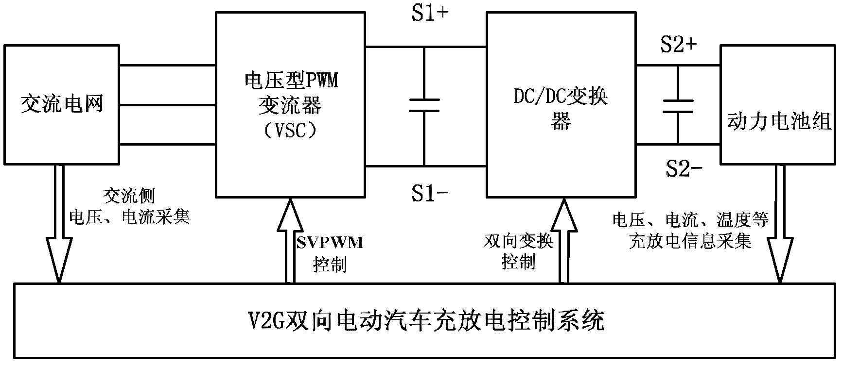
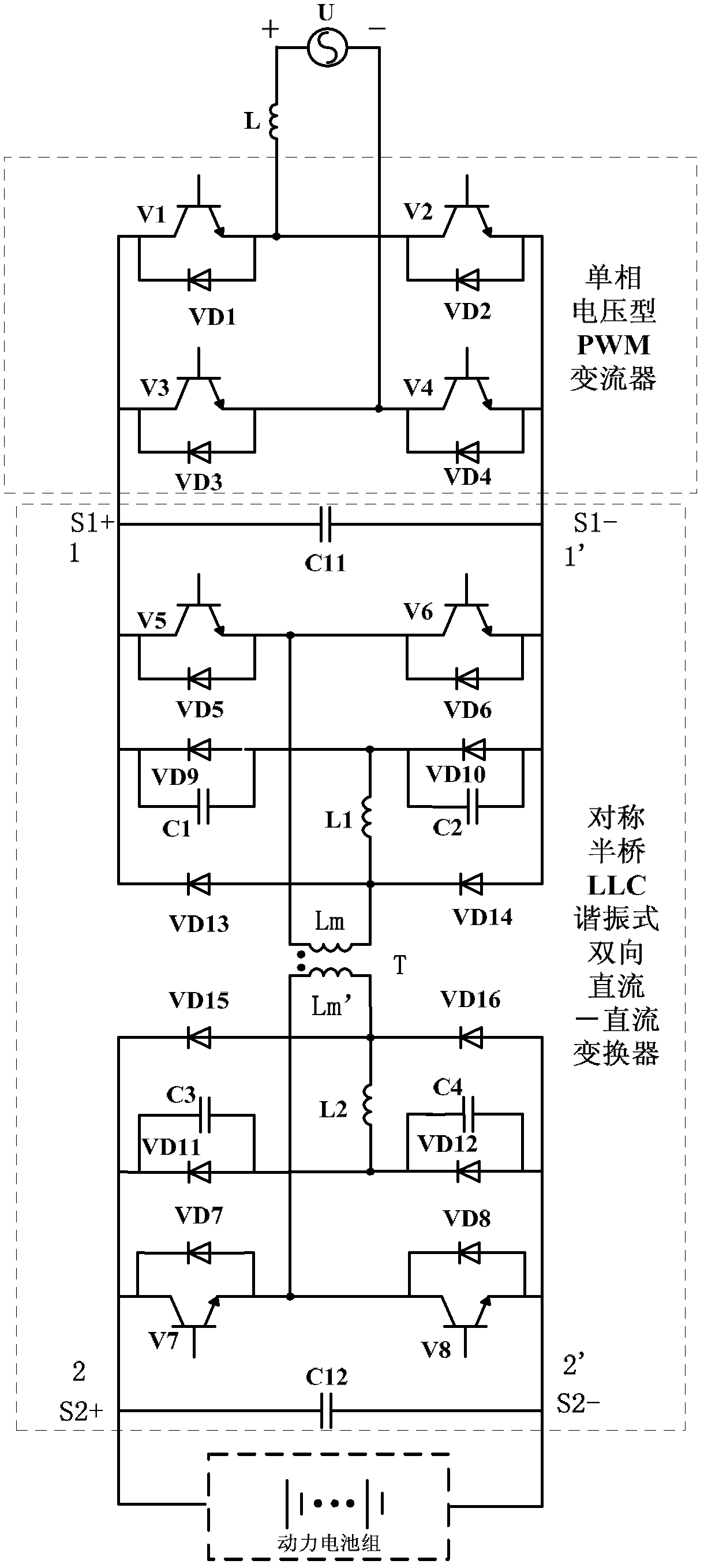
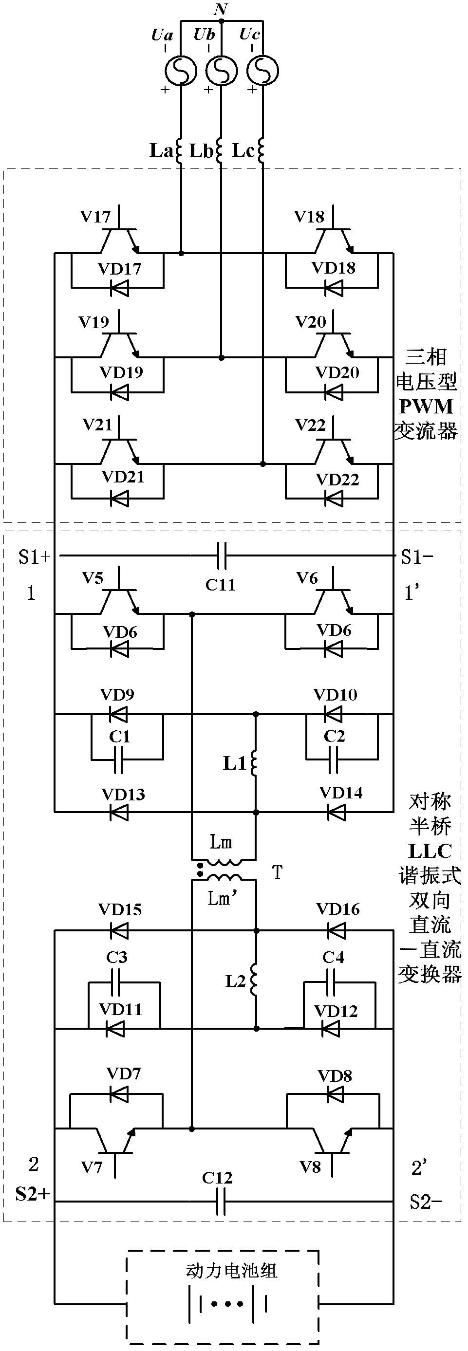
[0052] Such as figure 1 As shown, the invention discloses a V2G bidirectional power conversion electric vehicle charging and discharging system and a control method thereof. The main circuit adopts single-phase or three-phase voltage type PWM converter (VSC) as the first-level power conversion circuit to realize the connection between the AC power grid and the first DC bus (by the positive bus S1+ of the first DC bus and the negative bus of the first DC bus). The energy conversion between S1-composition) is referred to as "AC / DC converter" for short; the symmetrical half-bridge LLC resonant bidirectional DC-DC converter is used as the secondary power conversion circuit to realize the connection between the DC bus and the EV power battery pack. The energy conversion is referred to as "DC / DC converter" for short; the AC / DC converter and DC / DC converter are con...


PUM


Abstract

The invention discloses a charging-discharging system for a V2G bilateral power conversion electric automobile and a control method thereof, which belong to the technical field of intelligent power grids. In the charging-discharging system, a single-phase or three-phase voltage PWM (Pulse Width Modulation) converter (VSC) is taken as a first-grade power conversion circuit, so that energy conversion between an alternating-current power grid and a first direct-current bus is realized; and a symmetric half-bridge LLC (Logical Link Control) resonant bilateral direct current-direct current (DC / DC) converter is taken as a second-grade power conversion circuit, so that energy conversion between a direct-current bus and a power battery pack is realized. The charging-discharging system has the beneficial effects that: the current of the converter power grid side of the first-grade power conversion circuit is approximate to sine wave, so that the harmonic content is small; and the converting efficiency, dynamic performance and power density of the second-grade power conversion circuit are increased, the volume and weight of a charging-discharging device of the electric automobile are reduced, and the safety, reliability and economic efficiency of the system are improved effectively.

Description

technical field [0001] The invention belongs to the technical field of smart grids, and in particular relates to a V2G bidirectional power conversion electric vehicle charging and discharging system and a control method thereof. Background technique [0002] With the smart level of the power grid and the sharp increase in the number of electric vehicles, a large number of electric vehicle batteries may become distributed energy storage units in the smart grid in the future. Statistics show that an electric vehicle is in the idle state 95% of the time, The electric vehicle battery can be charged by the grid during the non-peak load period of the grid, and the electric vehicle battery can provide electric energy to the grid during the peak load period of the grid to obtain the price difference. Between car owners and system dispatchers, this technology that realizes intelligent charging and discharging management through real-time electricity prices and smart meters is V2G (Ve...

Claims


Application Information

Patent Timeline
IPC IPC(8): H02J7/02H02M7/219H02M3/335
Inventor 颜湘武张波肖湘宁陈征郭春林梁宇超
Owner NORTH CHINA ELECTRIC POWER UNIV (BAODING)
Learn More