Sludge multi-stage drying device, fluidized bed combustion treatment device and fluidized bed combustion treatment method

A sludge incineration and dryer technology, applied in combustion methods, dewatering/drying/concentrating sludge treatment, incinerators, etc. The effect of simplicity, small footprint, and low manufacturing costs

Active Publication Date: 2012-07-18
HARBIN HUAWEI HEAVY IND
View PDF10 Cites 16 Cited by
  • Summary
  • Abstract
  • Description
  • Claims
  • Application Information

AI Technical Summary

Problems solved by technology

[0005] The purpose of the present invention is to solve the problems of complex structure and large occupied area in the existing sludge dryer, as well as the problems of the heat in the sludg

Method used


Image

  • Sludge multi-stage drying device, fluidized bed combustion treatment device and fluidized bed combustion treatment method
  • Sludge multi-stage drying device, fluidized bed combustion treatment device and fluidized bed combustion treatment method
  • Sludge multi-stage drying device, fluidized bed combustion treatment device and fluidized bed combustion treatment method

Examples


specific Embodiment approach 1

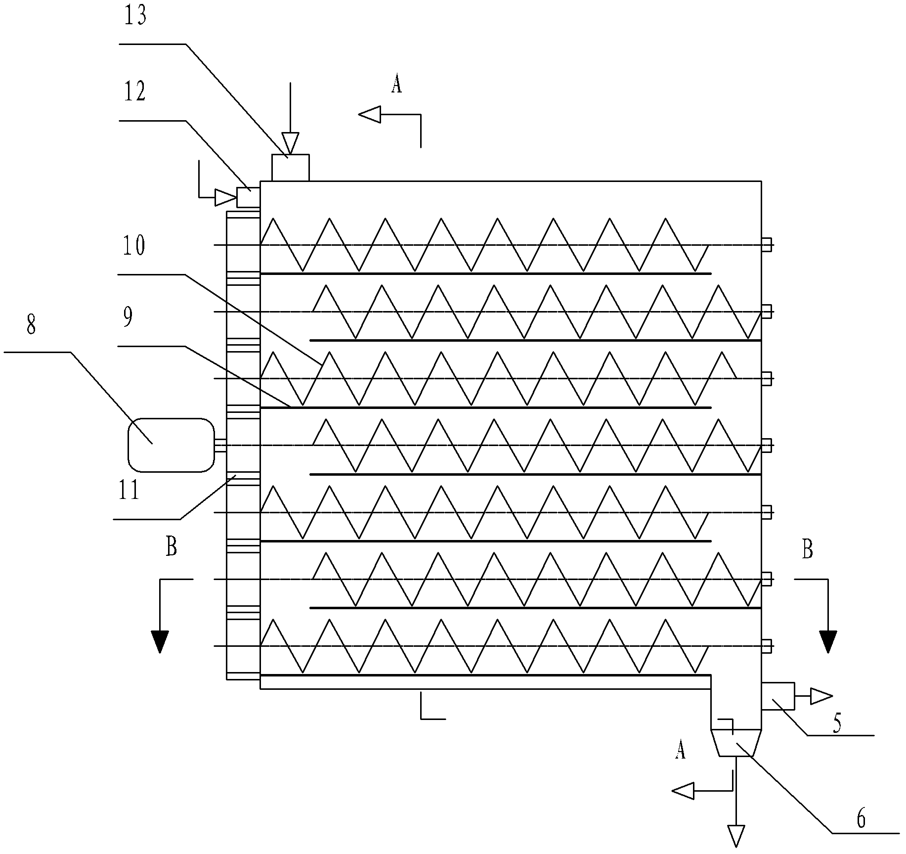
[0024] Specific implementation mode one: combine Figure 1 to Figure 3 To illustrate this embodiment, the sludge multi-stage dryer of this embodiment includes a drying chamber 23, a motor 8, a plurality of gears 11, at least three stages of augers, and an auger chassis 9 with the same number of stages as the auger;

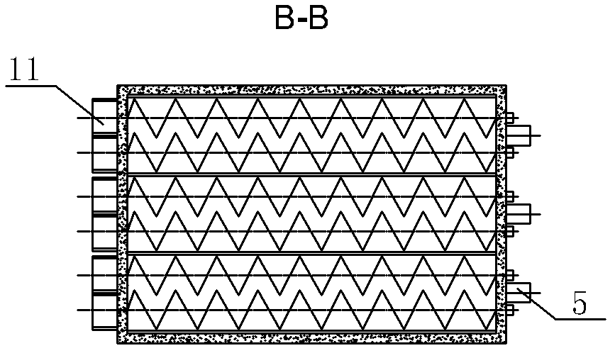
[0025] The at least three stages of augers are horizontally installed in the drying chamber 23 from top to bottom, adjacent augers on the same floor are arranged in a staggered manner, and an auger chassis 9 is arranged below each stage of auger 24, and the motor 8 is installed in the drying chamber On the outer wall of 23, the motor 8 establishes a transmission relationship with the augers at all levels through the gear 11. The upper cover of the drying chamber 23 is provided with a wet sludge inlet 13, and the upper part of the side wall of the drying chamber 23 is provided with a steam inlet 12. The drying chamber 23 A dry sludge outlet 6 is provided on the bot...

specific Embodiment approach 2

[0026] Specific implementation mode two: combination Figure 1 to Figure 3 To describe this embodiment, each stage of the auger in this embodiment includes a double auger 10 . Other compositions and connections are the same as in the first embodiment.

specific Embodiment approach 3

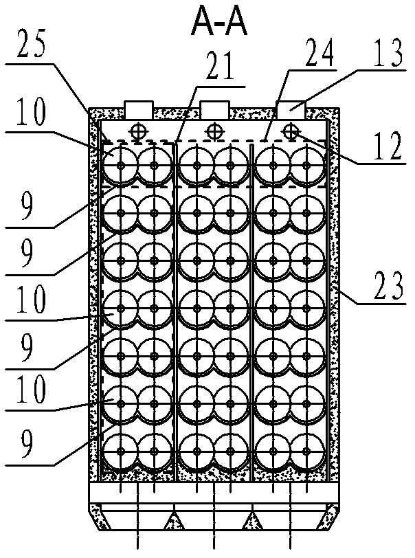
[0027] Specific implementation mode three: combination Figure 1 to Figure 3 Describe this embodiment, each level of auger in this embodiment includes a pair of augers, named double auger 10, the pair of augers are arranged side by side in the horizontal direction, and a transmission relationship is established between the two augers through a gear 11, The double augers 10 in the same row among at least three stages of augers are named drying section augers 25 , and a support member 21 is arranged between the two drying section augers 25 . With such a setting, the efficiency is high. Other compositions and connections are the same as in the first embodiment.

[0028] Specific implementation mode four: combination Figure 1 to Figure 3 Describe this embodiment, each level of auger in this embodiment includes a pair of augers, named double auger 10, the pair of augers are arranged side by side in the horizontal direction, and a transmission relationship is established between ...


PUM

PropertyMeasurementUnit
Calorific valueaaaaaaaaaa

Abstract

A fluidized bed combustion treatment device and method with a sludge multi-stage drying device belongs to the field of sludge treatment and aims at solving the problem that heat cannot be self-balanced and operation cost is high in the sludge combustion technology. The drying device is characterized in that at least three stages of packing augers are installed in a drying chamber, and a motor is installed on the drying chamber and builds a transmission relationship with the various stages of packing augers through gears. The treatment device and the treatment method are characterized in that a dry sludge storing cabin is arranged under a dry sludge outlet of the drying device, a steam outlet is connected with a cyclone separator, a large amount of steam is heated through a heat exchanger and then returns back to the drying device to continuous drying wet sludge, asmall amount of steam generates sewage after spraying dehydration through a spraying tower, the generated sewage is sent into a sewage treatment plant for treatment, non-condensable gas is burnt out after being sent into a fluidized bed combustion furnace, the air required in sludge combustion passes through the heat exchanger under effect of an air blower, then passes through an air preheater and is sent into the fluidized bed combustion furnace for combustion. The sludge multi-stage drying device, the fluidized bed combustion treatment device and the fluidized bed combustion treatment method are used in sludge treatment.

Description

technical field [0001] The invention relates to a sludge pollution-free treatment technology, in particular to a sludge multi-stage dryer, a fluidized bed incineration treatment device and a method. Background technique [0002] Sludge is the solid settling material produced by water and wastewater treatment processes. It generally contains a large amount of organic matter, heavy metals, pathogenic bacteria, etc., and is accompanied by a foul smell. my country discharges a large amount of industrial and urban domestic sewage every year. With the rapid development of economy, the increase of population and the continuous improvement of urbanization, the discharge of sewage will continue to increase. The annual dry sludge produced by urban sewage treatment plants in my country is about 25×10 4 t, based on wet sludge, is about 450~550×10 4 t, and grow at a rate of about 15% per year. Sludge contains a large amount of organic matter and rich nitrogen, phosphorus and other nu...

Claims


Application Information

Patent Timeline
IPC IPC(8): C02F11/12F23G7/00
Inventor 别如山黄兵宋兴飞纪晓俞朱少飞陈佩刘茜茜
Owner HARBIN HUAWEI HEAVY IND
Why Eureka
Try Eureka