Multi-layer structure

A multi-layer structure and layer structure technology, applied in the direction of layered products, synthetic resin layered products, household components, etc., can solve problems such as insufficient, poor appearance of molded objects, high melting point, etc. Excellent peel resistance and improved interlayer adhesion

Active Publication Date: 2012-07-18
MITSUBISHI CHEM CORP
View PDF6 Cites 3 Cited by
  • Summary
  • Abstract
  • Description
  • Claims
  • Application Information

AI Technical Summary

Problems solved by technology

[0004] However, since the above-mentioned polyvinyl alcohol-based resin has a melting point close to its decomposition point, for example, when it is desired to obtain a molded product by melt molding, the appearance of the obtained molded product is poor due to the occurrence of foreign matter and charring. Therefore, in order to solve these problems For example, it is proposed that the total amount of polyvinyl alcohol and alkali metal salt with a degree of polymerization of 200-1200, a degree of saponification of 75-99.99 mol%, and a melting point of 160-230°C with a terminal carboxyl group and a terminal lactone ring of 0.008-0.15 mol% Polyvinyl alcohol-based resin composition for melt molding (see Patent Document 1)
[0005] However, in the polyvinyl alcohol-based resin composition disclosed in the above-mentioned Patent Document 1, the melting point of the fully saponified product is still about 200 to 230° C., which is high enough to solve the above-mentioned problems.

Method used


Image

  • Multi-layer structure
  • Multi-layer structure
  • Multi-layer structure

Examples


Embodiment 1

[0257]

[0258] As the layer (A) forming material shown below, the above-mentioned PET-based resin (IS654) was used, and as the layer (B) forming material, the above-mentioned PVA-based resin (B1-x) was used, and a T-die with two types and three layers was used. A melt extrusion molding machine was used to produce a layer (A) / layer (B) / layer (A) with a layer (A) thickness of 40 μm, a layer (B) thickness of 20 μm, and a layer (A) thickness of 40 μm. Laminated body (film form) with a 3-layer structure (total thickness: 100 μm).

[0259] In addition, extrusion is carried out at a mold temperature of 260°C at a resin temperature of 260 to 280°C for PET-based resins and 240°C for PVA-based resins. A multilayer structure is obtained.

[0260]

[0261] Using the obtained three-layer structure (film), the peel strength between the layer (A) and the layer (B) was measured under the following conditions. The results are shown in Table 1 below.

[0262] Sample: 15mm wide, 200mm lo...

Embodiment 2

[0267] As a layer (A) forming material, PET-based resin, the above-mentioned IG395Z (AV value 28) having a copolymerization ratio of isophthalic acid of 15.0 mol % was used. Except for this, a three-layer structure was produced in the same manner as in Example 1, and evaluated in the same manner. The results are shown in Table 1 below.

Embodiment 3

[0279] A three-layer structure was produced in the same manner as in Example 1 except that the PVA-based resin (B2-x) was used as the layer (B)-forming material in Example 1, and evaluated in the same manner. The results are shown in Table 2 below.


PUM

PropertyMeasurementUnit
melting pointaaaaaaaaaa
degree of polymerizationaaaaaaaaaa

Abstract

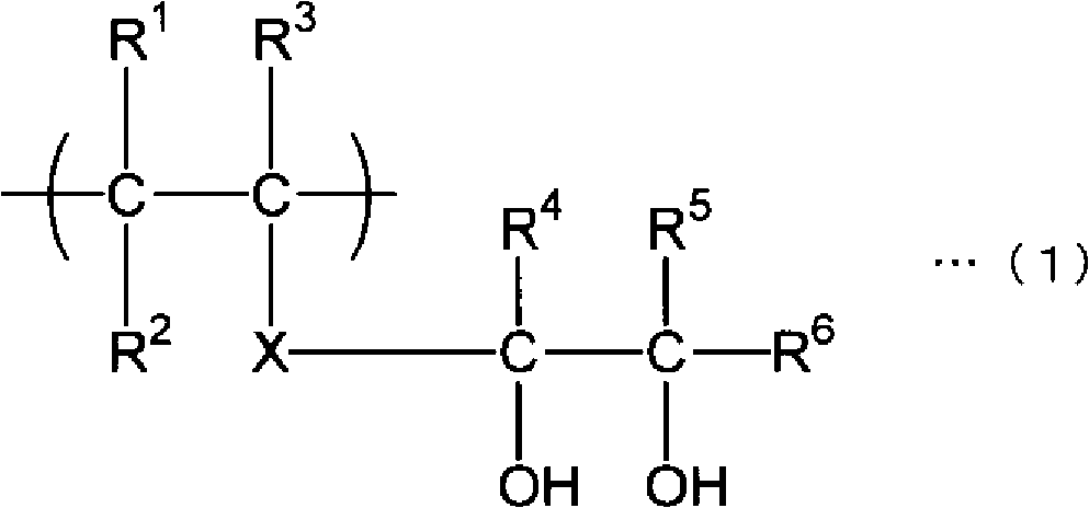
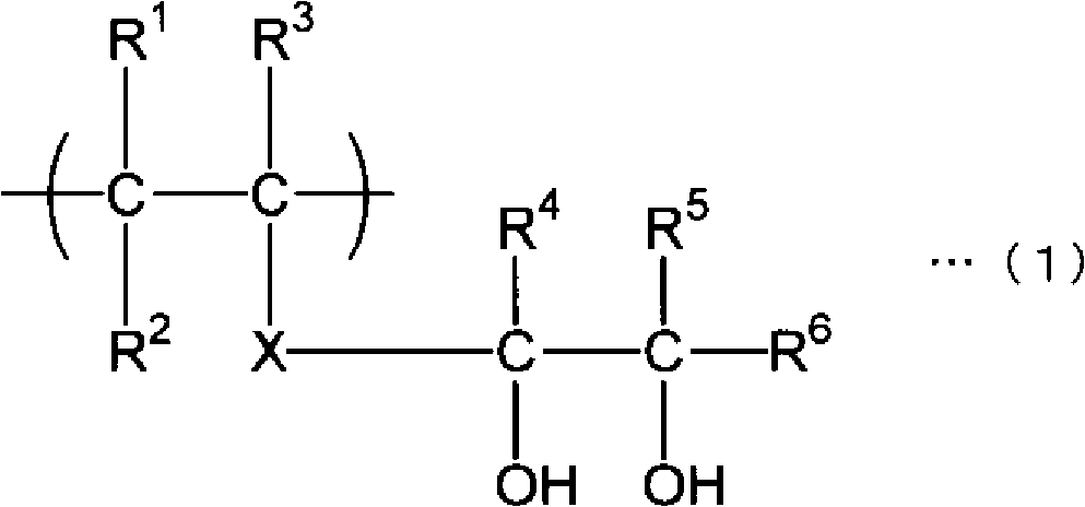
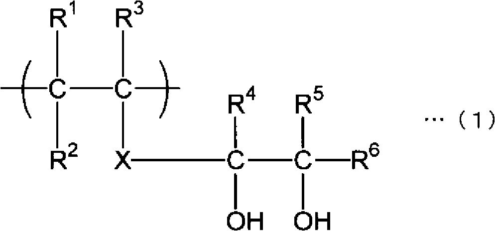
Provided is a multi-layer structure comprising the following layers: a layer (A) consisting primarily of a polyethylene terephthalate resin, which comprises a dicarboxylic acid component that contains terephthalic acid and a diol component that consists primarily of ethylene glycol, wherein the copolymer fraction of non-terephthalic-acid dicarboxylic acids in the dicarboxylic acid component is 15-40 mol% of the entire dicarboxylic acid component; and a layer (B) that is adjacent to the abovementioned layer (A) and consists primarily of a polyvinyl alcohol resin having the structural unit represented by general formula (1). This results in increased interlayer adhesion between the layers (A and B), yielding a multi-layer structure that is highly resistant to separation of the layers thereof. (1) (In formula (1), R1, R2, and R3 each independently represent a hydrogen atom or an organic group, and X represents a single bond or a bond chain. R4, R5, and R6 each independently represent a hydrogen atom or an organic group.)

Description

technical field [0001] The present invention relates to a multilayer structure having a layer mainly composed of a polyethylene terephthalate resin and a layer mainly composed of a polyvinyl alcohol resin, and these layers are excellent in interlayer adhesiveness. Background technique [0002] Generally, polyvinyl alcohol-based resins are excellent in transparency, barrier properties, and the like, and by utilizing such properties effectively, they can be molded into films, sheets, etc., and used in various packaging materials. Furthermore, for containers such as bottles requiring high gas barrier properties, conventionally, containers having a multilayer structure having polyvinyl alcohol-based resin layers between polyethylene terephthalate-based resins have been used. [0003] The above multilayered container is obtained by co-melt extrusion of a polyvinyl alcohol-based resin and a polyethylene terephthalate-based resin. [0004] However, since the above-mentioned polyvi...

Claims


Application Information

Patent Timeline
Patent Type & Authority Applications(China)
IPC IPC(8): B32B27/36B32B27/30
CPCB32B27/36B32B27/28B32B27/08B32B27/18B32B27/285B32B27/306B32B2250/42B32B2307/50B32B2307/7166B32B2307/748B32B2439/00B32B2439/70B32B2439/80B32B2553/00Y10T428/31797
Inventor 川边雅之涩谷光夫井上馨酒井纪人
Owner MITSUBISHI CHEM CORP
Why Eureka
Try Eureka