Pulse driving power supply of high-power semiconductor laser

A pulse drive, semiconductor technology, applied in the direction of semiconductor lasers, lasers, laser parts, etc., can solve the problem of small output current and achieve the effect of good edge characteristics

Inactive Publication Date: 2012-08-01
JILIN UNIV
View PDF7 Cites 20 Cited by
  • Summary
  • Abstract
  • Description
  • Claims
  • Application Information

AI Technical Summary

Problems solved by technology

However, in the related design disclosed above, the output current is in the form of constant curr

Method used


Image

  • Pulse driving power supply of high-power semiconductor laser
  • Pulse driving power supply of high-power semiconductor laser
  • Pulse driving power supply of high-power semiconductor laser

Examples


Embodiment 1

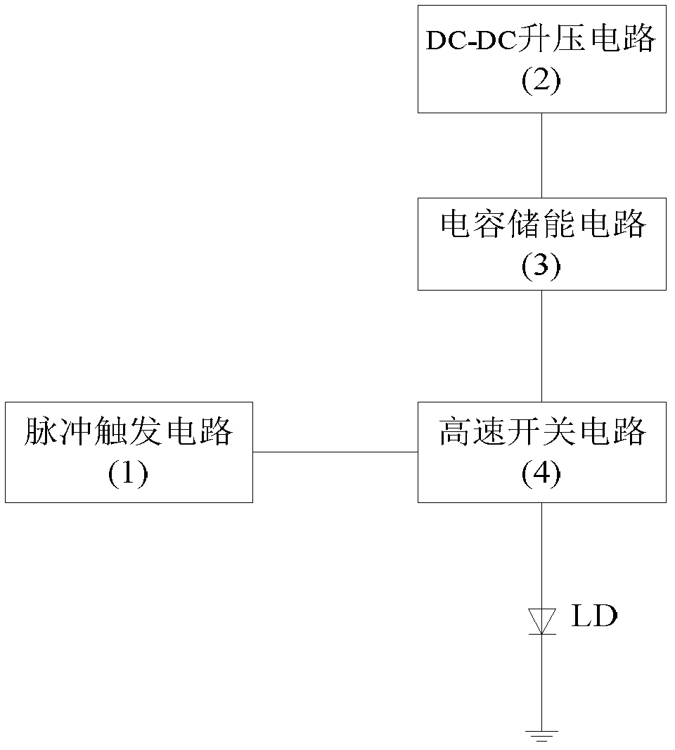
[0022] Embodiment 1 illustrates the overall structure of the present invention in conjunction with the accompanying drawings

[0023] The high-power semiconductor laser pulse drive power supply of the present invention is composed of four parts: a pulse trigger circuit 1, a DC-DC boost circuit 2, a capacitor energy storage circuit 3, and a high-speed switch circuit 4. The structural block diagram is as follows figure 1 shown. Wherein the DC-DC step-up circuit 2 generates a high-voltage direct current voltage, which is connected to the capacitor energy storage circuit 3. The capacitor energy storage circuit stores energy and is connected to the high-speed switch circuit 4. Under the control of the signal, the energy stored in the capacitor energy storage circuit 3 is released, so that a narrow pulse with a large current value is obtained on the load LD.

Embodiment 2

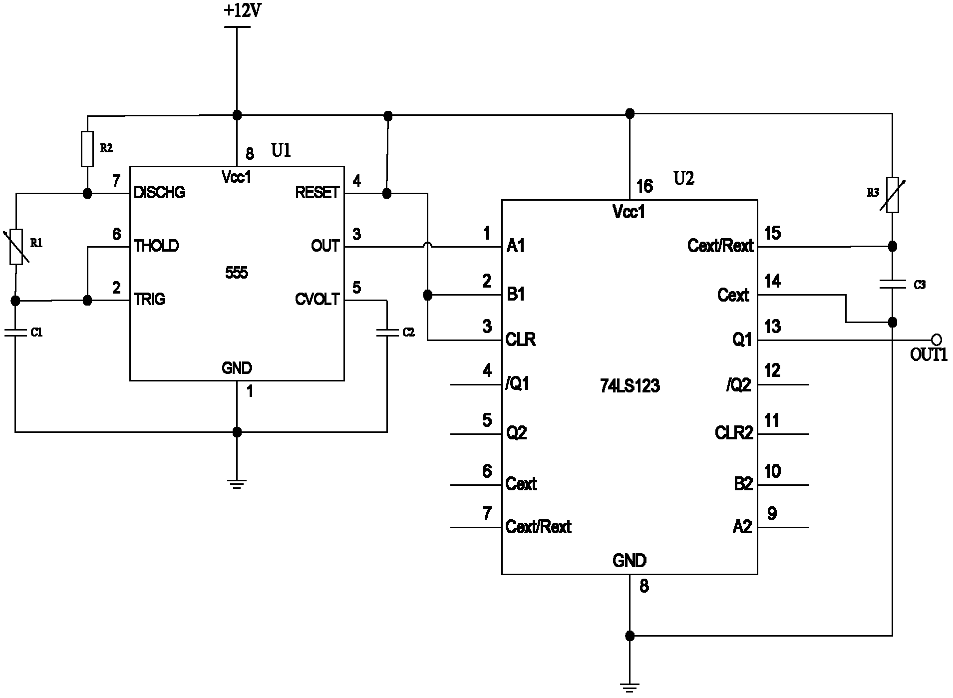
[0024] Embodiment 2 Pulse Trigger Circuit 1

[0025] Such as figure 2 As shown, pulse trigger circuit 1 includes: pin 1 of 555 chip U1 is grounded, one end of capacitor C1 and C2 is connected to pin 1 of 555 chip U1, the other end of C1 is connected to pin 2 of 555 chip U1, and the other end of C2 is connected to pin 1 of 555 chip U1. The 5 pins of the 555 chip U1 are connected, the 2 pins of the 555 chip U1 are connected with the 6 pins of the 555 chip U1, one end of the variable resistor R1 is connected with the 2 pins of the 555 chip U1, and the other end is connected with the 7 pins of the 555 chip U1. One end of resistor R2 is connected to pin 7 of 555 chip U1, and the other end is connected to pin 8 of 555 chip U1. Pin 8 of 555 chip U1 is connected to +12V power supply and connected to pin 4 of 555 chip U1. Pin 3 of 555 chip U1 is connected with pin 1 of 74LS123 chip U2, pin 16 of 74LS123 chip U2 is connected with pin 8 of 555 chip U1, pin 2 and pin 3 of 74LS123 chip U...

Embodiment 3D

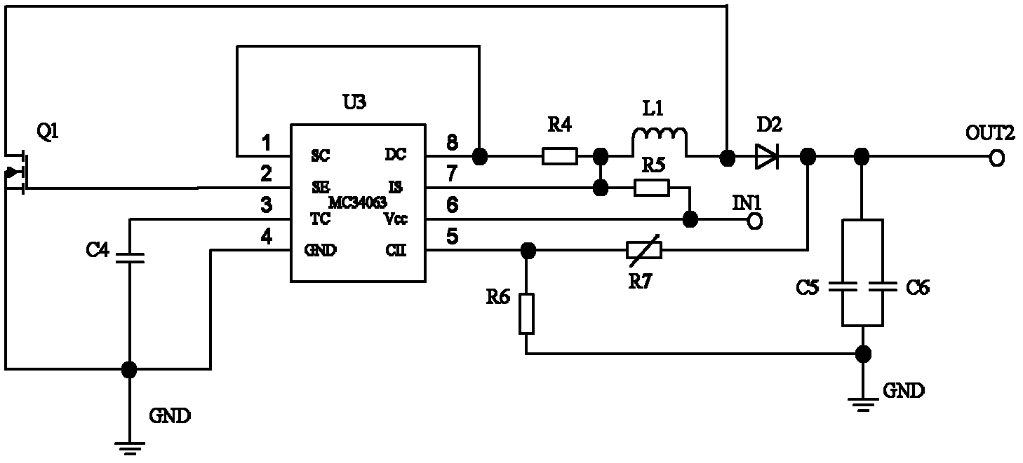
[0027] Embodiment 3 DC-DC boost circuit 2

[0028] Such as image 3As shown, the DC-DC boost circuit 2 includes: MC34063 chip U3’s pin 1 is connected to pin 8, pin 2 is connected to the gate of field effect transistor Q1, the source of Q1 is connected to ground GND and connected to one end of capacitor C4, and the other end of C4 One end is connected to pin 3 of MC34063 chip U3, and pin 4 of MC34063 chip U3 is connected to ground GND. Pin 8 of MC34063 chip U3 is connected to one end of resistor R4, and the other end of R4 is connected to pin 7 of MC34063 chip U3, and connected to one end of inductor L1, and the other end of inductor L1 is connected to the drain of field effect transistor Q1, and connected to the anode of diode D2 , the cathode of diode D2 is connected to one end of variable resistor R7, and grounded through two parallel capacitors C5 and C6, and the other end of R7 is connected to pin 5 of MC34063 chip U3, and grounded through resistor R6. One end of resisto...


PUM

PropertyMeasurementUnit
Capacitanceaaaaaaaaaa
Resistanceaaaaaaaaaa

Abstract

The invention relates to a pulse driving power supply of a high-power semiconductor laser, belonging to the technical field of electronic equipment. The pulse driving power supply structurally comprises a pulse trigger circuit (1), a DC-DC boost circuit (2), a capacitive energy storage circuit (3), a high-speed switching circuit (4) and the like, wherein the capacitive energy storage circuit (3) is formed by connecting a plurality of capacitors in parallel; and the high-speed switching circuit (4) adopts a high-speed MOSFET (Metal Oxide Semiconductor Field Effect Transistor) element as a switching device. According to the pulse driving power supply for driving the semiconductor laser, provided by the invention, the output current is more than or equal to 50 amperes, the output pulse current rise time is more than or equal to 30 nanoseconds, the pulse current width is more than or equal to 15 nanoseconds, and the maximum repetition frequency is 4KHz; favorable edge property of the output current pulse is ensured by adopting the high-speed MOSFET element as the switching device; and the plurality of capacitors are connected in parallel to form an energy storage current to realize output of high current and narrow pulse signals.

Description

technical field [0001] The invention belongs to the technical field of electronic equipment, and in particular relates to a high-power pulse driving power supply for semiconductor lasers. Background technique [0002] High-power semiconductor lasers are necessary pump light sources for solid-state lasers in industrial production, military defense and other industries. They are widely used in laser ranging, nuclear explosion simulation, lidar transmission, material processing, microprocessing, heat treatment, marking positioning, etc. In addition, high-power lasers are also widely used in medical fields such as surgical treatment of tumors, skin treatment, dental treatment, photoanalgesia, photoacupuncture, and optical tomography (OCT). The performance of semiconductor lasers is affected by temperature factors, and its output efficiency decreases with the increase of its own temperature. That is to say, semiconductor lasers are very sensitive to temperature. If the temperatur...

Claims


Application Information

Patent Timeline
IPC IPC(8): H02M9/04H01S5/042
Inventor 单江东高博田小建汝玉星吴戈
Owner JILIN UNIV
Why Eureka
Try Eureka