Micro-thermal photovoltaic system for cooling based on heat pipe principle

A technology based on the principle of micro-thermal photoelectricity and heat pipe, which is used in photovoltaic power generation, optical radiation generators, photovoltaic modules, etc.

Inactive Publication Date: 2012-08-15
JIANGSU UNIV
View PDF4 Cites 3 Cited by
  • Summary
  • Abstract
  • Description
  • Claims
  • Application Information

AI Technical Summary

Problems solved by technology

The defect of existing micro burner is; 1, when the burner of conventional scale is reduced to several cubic centimeters, flame is confined in the narrow space, and hydrogen and oxygen (air) mixing degree weakens, shortens the residence time in burner, easily Incomplete combustion occurs, resulting in low radiator surface temperature and low energy conversion efficiency
2. As the size of the combustion chamber decreases, the surface area and volume ratio of the combustion chamber increase significantly, which causes a sharp increase in the heat dissipation loss of the micro burner, reduces the flame temperature, and then affects the flame stability and flameout, and the thermal efficiency decreases

Method used


Image

  • Micro-thermal photovoltaic system for cooling based on heat pipe principle
  • Micro-thermal photovoltaic system for cooling based on heat pipe principle
  • Micro-thermal photovoltaic system for cooling based on heat pipe principle

Examples


Embodiment Construction

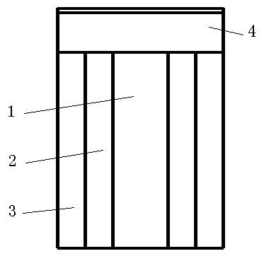
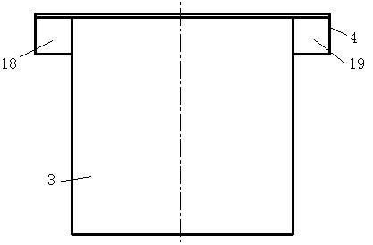
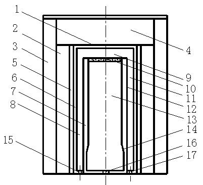
[0019] Such as figure 1 with figure 2 As shown, the present invention is made up of four parts: micro burner 1, photovoltaic cell 2, flat heat pipe 3 and gas cooling system 4, and the uppermost part is gas cooling system 4, and micro burner 1 is positioned at just below gas cooling system 4 and is connected with gas The cooling system 4 is connected.

[0020] Such as Figure 1-3 Shown, micro-combustor 1 comprises glass cover 6 and micro-combustion chamber 13, and glass cover 6 adopts organic quartz glass, and micro-combustion chamber 13 is set in the inner chamber of glass cover 6, and glass cover 6 and micro-combustion chamber The bottom surface of 13 is flush, and all leaves space between the both sides of glass cover 6 and micro-combustion chamber 13 and the top. The micro-combustion chamber 13 is made up of the micro-combustion chamber shell 7 and the porous medium panel 10, and the micro-combustion chamber shell 7 adopts SiC ceramics with strong high temperature resi...


PUM


Abstract

The invention discloses a micro-thermal photovoltaic system for cooling based on a heat pipe principle. A micro burner comprises a glass shielding cover and a micro burning chamber arranged in an inner cavity of the glass shielding cover; gaps are reversed among two sides and the tops of the glass shielding cover and the micro burning chamber; a top board of a shell of the micro burning chamber is a porous medium panel; the inner side wall of the shell of the micro burning chamber at the position of a bottom board of the shell of the micro burning chamber is thinned to form a sudden expansion structure; a glass insulating layer is tightly connected with one side of a photo cell, and the other side of the photo cell is in seamless connection with a panel heat pipe; a hydrogen inlet and an oxygen inlet which are communicated with the gap between the glass shielding cover and the micro burning chamber are formed on a bottom board of the glass shielding cover; an air cooling system is arranged above the micro burning chamber; the bottom surface of a cooling channel is formed by combining the glass shielding layer, the glass insulating layer and the top surface of the photo cell; and the left side surface and the right side surface of the cooling channel are the internal side surface of the panel heat pipe. Therefore, the burning reaction speed and the burning efficiency can be improved, the uniform temperature field distribution is obtained, and the heat loss of the burner is reduced.

Description

technical field [0001] The invention belongs to the field of micro-power electromechanical systems, and in particular relates to a micro-thermal photoelectric system. Background technique [0002] The micro-thermal photoelectric system consists of a micro-burner, a photoelectric conversion system, and a cooling channel for photovoltaic cells. Hydrogen and oxygen are burned in the micro-burner to release chemical energy, so that the wall of the burner is at a high temperature, and the outer surface of the micro-burner is selectively coated. Layer material, which can emit a certain wavelength of spectrum, is absorbed by the semiconductor photovoltaic material and performs photoelectric conversion to realize the output of electric energy. The whole process is concentrated in a space of tens of cubic centimeters or even several cubic centimeters, and the energy density is high (10 times that of lithium batteries. above), simple structure, low cost and stable voltage. [0003] ...

Claims


Application Information

Patent Timeline
Patent Type & Authority Applications(China)
IPC IPC(8): H02N6/00F28D15/02H02S40/42
CPCY02E10/50
Inventor 吴鸽平虞永川马春花陆平黄河张敏
Owner JIANGSU UNIV
Why Eureka
Try Eureka