Novel high-power light emitting diode (LED) light source structure based on non-metal-based printed circuit board

An LED light source, non-metal technology, applied in the field of LED semiconductor lighting, can solve the problems of high interface thermal resistance, low heat generation, and the interface 1 is not tightly attached, so as to reduce interface thermal resistance, chip junction temperature, and production cost. low cost effect

Inactive Publication Date: 2012-09-12
TIANJIN POLYTECHNIC UNIV
View PDF0 Cites 5 Cited by
  • Summary
  • Abstract
  • Description
  • Claims
  • Application Information

AI Technical Summary

Problems solved by technology

However, this assembly structure often has the following problems: (1) The heat generated by the LED must be dissipated to the surrounding environment through the package base → thermal grease filling interface 1 → MCPCB → thermal grease filling interface 2 → radiator, the heat flow The path is long, and the thermal resistance of the sub-structure and the interface are more; (2) It is difficult to minimize the thickness of the thermal grease layer under the LED base only by relying on the weak fastening force generated after the LED pins are soldered, causing the interface 1. The bonding is not tight, even there are obvious gaps, and the interface thermal resistance is high; (3) The MCPCB has a large area, and a large amount of thermal conductive silicone grease must be applied when assembling with the radiator, and air bubbles need to be removed when the screws are fastened. and excess silicone grease are discharged from the interface. Due to the high price of thermal conductive silicone grease, the consumption is large, and the assembly cost is high; and the fluidity of the silicone grease is poor. The uneven thickness of silicone grease occurs, which brings about the consequences of large thermal resistance of interface 2 and poor regional consistency
[0005] Similarly, MCPCB itself also has some shortcomings: (1) The dielectric layer inside the MCPCB is a polymer composite material, and its thermal conductivity is too low, which has become a bottleneck for heat conduction through MCPCB; (2) The temperature resistance of the dielectric layer material Poor, it should not exceed 250°C to 300°C during the manufacturing process, so the temperature control parameters of the soldering process must be adjusted in advance when passing through the tin furnace;
[0006] (3) The manufacture of MCPCB requires a large amount of metal materials as the substrate, and the process is complicated, which makes the cost of the lamp board high, limits its market development potential, and affects the popularization of high-power LED light sources to ordinary users
However, due to the poor thermal conductivity of non-metallic substrates, it is limited to the production of low-power LED lamp panels that generate little heat and have almost no heat dissipation problems. Therefore, in order to apply it to high-power LED light sources, the relevant structural design must be improved. , thus significantly improving the heat dissipation capacity of the light source system while realizing the electrical connection and mechanical load-bearing functions

Method used


Image

  • Novel high-power light emitting diode (LED) light source structure based on non-metal-based printed circuit board
  • Novel high-power light emitting diode (LED) light source structure based on non-metal-based printed circuit board
  • Novel high-power light emitting diode (LED) light source structure based on non-metal-based printed circuit board

Examples


Embodiment 1

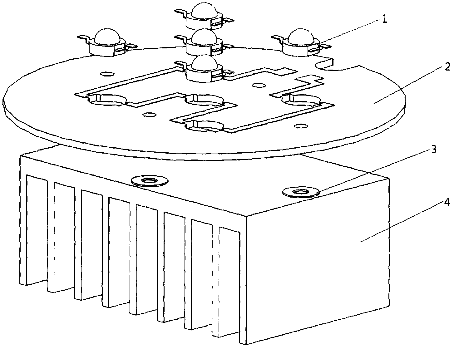
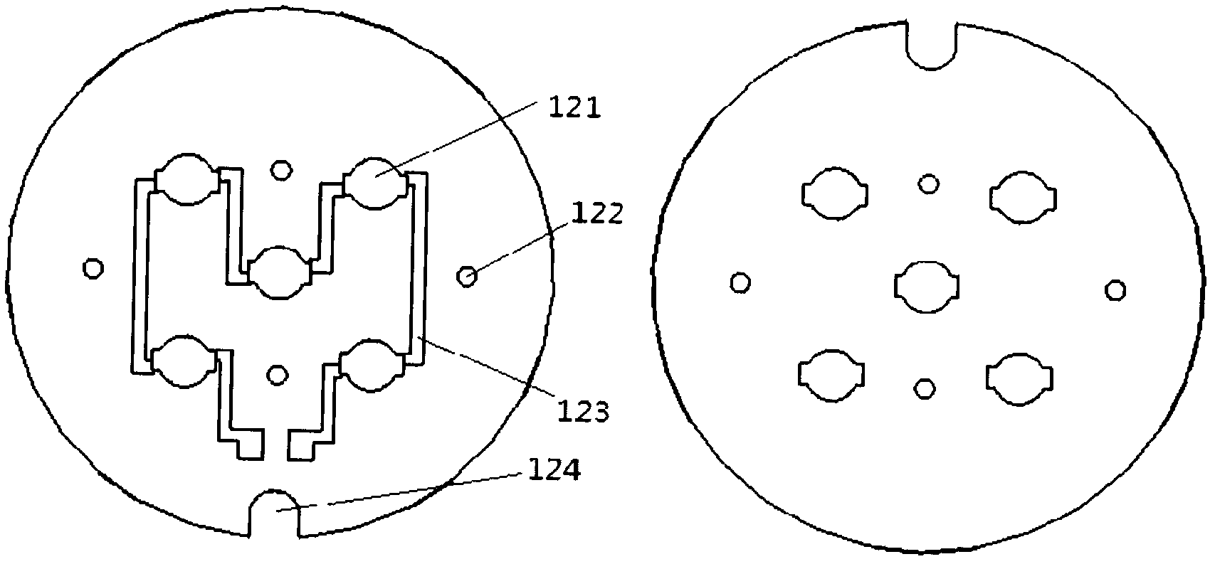
[0022] such as explosion figure 1 As shown, a new structure of high-power LED light source based on non-metal base circuit board, including LED1, non-metal base PCB2, gasket 3, and heat sink 4. Wherein, the pin 113 of the LED1 is upward, and the LED installation through hole 121 is provided on the PCB2, and the diameter of the through hole 121 is slightly larger than the diameter of the plastic bracket 112 of the LED1. The front side of the PCB 2 is coated with copper 123 , and the front side is a light-emitting surface. The gasket 3 is preferably a non-metallic flat gasket with strong deformation resistance. Each through hole 121 on the PCB2 is correspondingly embedded with an LED1, and the pin 113 of the LED1 is soldered to the copper foil 123 on both sides of the corresponding through hole to form an electrical connection. The base 114 of the LED1 can be in direct contact with the top 141 of the heat sink through the through hole. The base 114 is coated with heat-conduct...

Embodiment 2

[0024] such as explosion Figure 6As shown, a new structure of high-power LED light source based on non-metal base circuit board, including LED5, non-metal base PCB6, insulating gasket 7, and radiator 4. Wherein the pin 253 of the LED5 is downward, and the LED installation through hole 261 is arranged on the PCB 6 , and the diameter of the through hole 261 is slightly larger than the diameter of the plastic bracket 252 of the LED5. Copper 264 is covered on the reverse side of the PCB 6 , and the reverse side is a non-light-emitting surface. Each through hole 261 on the PCB6 is correspondingly embedded with an LED5, and the pin 253 of the LED5 is located on the opposite side of the PCB6, and is soldered to the copper foil 264 on both sides of the corresponding through hole to form an electrical connection. An insulating spacer 7 is installed between the PCB 6 and the top 141 of the heat sink, and the insulating spacer 7 mainly plays the role of pin insulation and fastening. T...


PUM


Abstract

The invention discloses a novel high-power light emitting diode (LED) light source structure based on a non-metal-based printed circuit board (PCB). The novel high-power LED light source structure mainly comprises high-power LEDs, non-metal-based PCBs, a radiator, and a corresponding insulating spacer or gasket which is added according to the needs of electrical insulation and fastening degree control, wherein LEDs have a thermoelectrically separated pin type packaging structure, the pins can be bent toward the direction of a lens or a base, provide electrical connection and provide high fastening force; the non-metal-based PCBs are common hard single-sided copper-clad plates and are provided with LED assembling through holes which have the same number as that of the LEDs, and two sides of each assembling through hole are uniformly provided with circuits and pads; and therefore, the welded LEDs can give out light outwards through the assembling through holes, and the assembling through holes have the functions of clamping the LEDs at fixed points and can provide high fastening force. The LED bases with the novel structure can be directly contacted with the radiator, so that the radiating thermal resistance is obviously reduced.

Description

technical field [0001] The invention relates to a new structure of an LED light source, in particular to a new structure of a high-power LED light source based on a non-metallic circuit board to achieve good electrical connection, physical bearing and heat dissipation effect, and can be widely used in the field of LED semiconductor lighting. Background technique [0002] LED (Light Emitting Diode) semiconductor light-emitting device has many performance advantages that traditional light sources cannot match. It is a new generation of "green lighting" light source that meets energy conservation and environmental protection. At present, in order to realize the large-scale replacement of traditional lamps by LED light sources and open up a huge general lighting market, LEDs need to greatly increase their input power to achieve higher luminance. However, with the continuous improvement of input electric power, the chip area of ​​high-power LED (≥1W) will produce up to 100W / cm 2...

Claims


Application Information

Patent Timeline
Patent Type & Authority Applications(China)
IPC IPC(8): F21S2/00F21V29/00F21V17/12F21V23/00F21Y101/02F21K9/20F21V29/503F21V29/76F21Y115/10
Inventor 张建新牛萍娟杨庆新李红月孙连根
Owner TIANJIN POLYTECHNIC UNIV
Why Eureka
Try Eureka