Water heat-transfer shift process for by-product high-grade steam energy-saving deep conversion

A high-grade, steam technology, applied in the field of , can solve the problems of over-temperature catalyst, hidden danger of system operation, short service life of catalyst, etc., and achieve the effect of facilitating self-unloading of catalyst, preventing dew point corrosion, and easy temperature control.

Active Publication Date: 2012-10-03
NANJING DUNXIAN CHEM TECH
View PDF4 Cites 32 Cited by
  • Summary
  • Abstract
  • Description
  • Claims
  • Application Information

AI Technical Summary

Problems solved by technology

[0005] (2) It is difficult to determine the catalyst loading amount of the first-stage adiabatic converter: it is limited by the "activity coefficient (TF)": TF is an empirical value, and the data after actual application is required to check
When selecting the amount of catalyst for the "one-stage adiabatic converter", if the TF is selected to be large, the amount of catalyst will be less, and the conversion rate of the "one-stage adiabatic converter" will not meet the requirements, which will increase the load on the subsequent converter, and the heat energy recovery and design of the system The deviation between the values ​​is very large; if TF is small, the amount of catalyst used in the "one-stage adiabatic shift furnace" will be large, and the "one-stage adiabatic shift furnace" will be overheated (catalyst burnout is likely to occur), and methane will be brought Chemical side reactions increase and bring great safety hazards to system operation
[0006] (3) In addition, t

Method used


Image

  • Water heat-transfer shift process for by-product high-grade steam energy-saving deep conversion
  • Water heat-transfer shift process for by-product high-grade steam energy-saving deep conversion
  • Water heat-transfer shift process for by-product high-grade steam energy-saving deep conversion

Examples


Embodiment 1

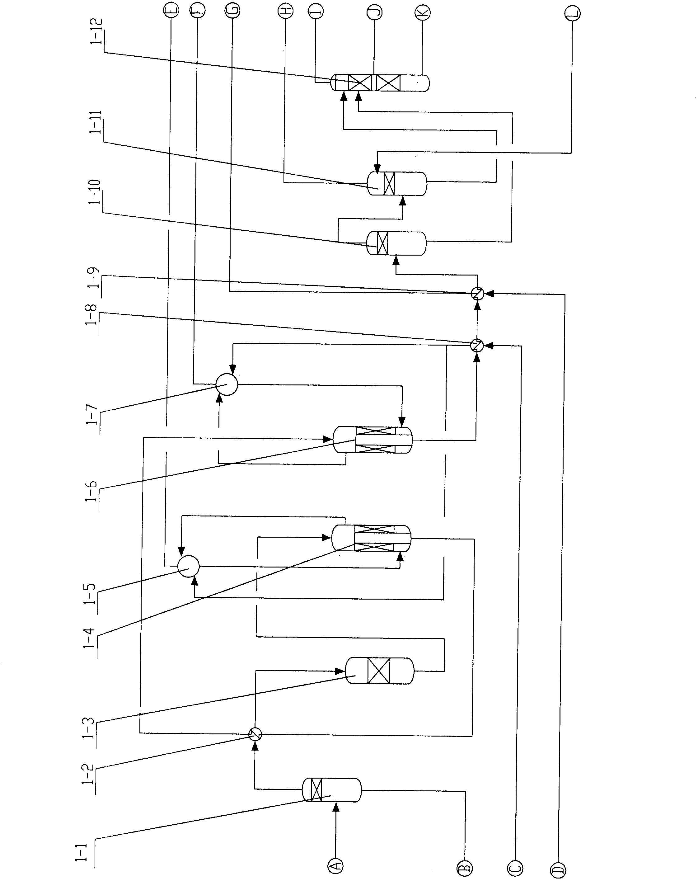
[0054] as attached figure 1 As shown, the raw material gas from the gasification device enters the interior of 1# gas-liquid separator 1-1 for downward swirling (the gas swirls downward to facilitate separation), and after the dust and water are separated, they reverse 180° and enter the center pipe, and then It is further filtered through a stainless steel wire mesh to ensure that the gas is clean.

[0055] The raw gas coming out of 1# liquid separator 1-1 enters the raw gas heater 1-2 for heat exchange, and when the temperature reaches 240°C (feed temperature ≥ dew point temperature 30°C), it enters the detoxification tank 1-3, and the gas passes through the upper detoxification tank. After the poison is detoxified, it directly enters a small amount of catalyst bed in the lower part for reaction, and the temperature rises to 300°C (the reaction temperature is controlled by the amount of catalyst loading ≤ 300°C), and this part of the catalyst is used to further absorb and re...

Embodiment 2

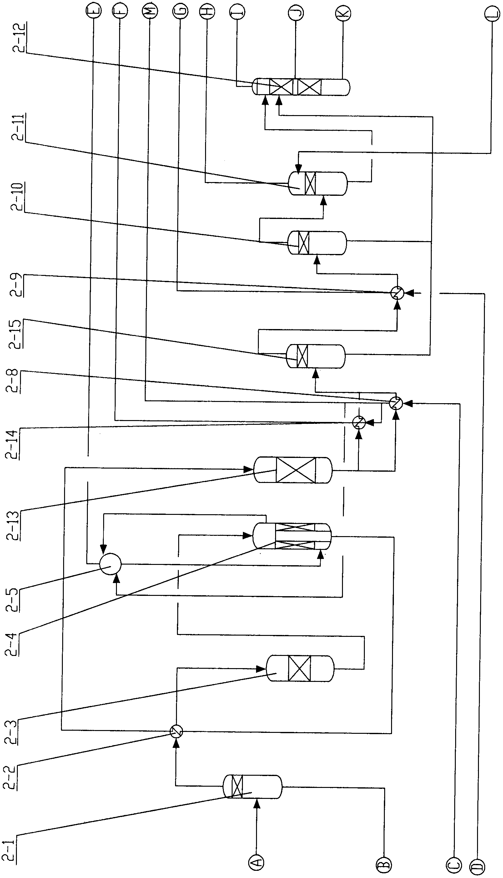
[0062] as attached figure 2 As shown, the raw material gas from the gasification device enters the interior of 1# gas-liquid separator 2-1 for downward swirl flow (the gas swirls downward to facilitate separation), and the dust and water are separated and reversed 180° into the center pipe, and then It is further filtered through a stainless steel wire mesh to ensure that the gas is clean.

[0063] The raw material gas from the 1# liquid separator 2-1 enters the raw gas heater 2-2 for heat exchange, and when the temperature reaches 300°C (feed temperature ≥ dew point temperature 30°C), it enters the detoxification tank 2-3, and the gas passes through the upper detoxification tank. After the poison is detoxified, it directly enters a small amount of catalyst bed in the lower part for reaction, and the temperature rises to ~300°C. This part of the catalyst is used to further absorb and remove harmful substances in the water gas under high temperature conditions. The gas exitin...

Embodiment 3

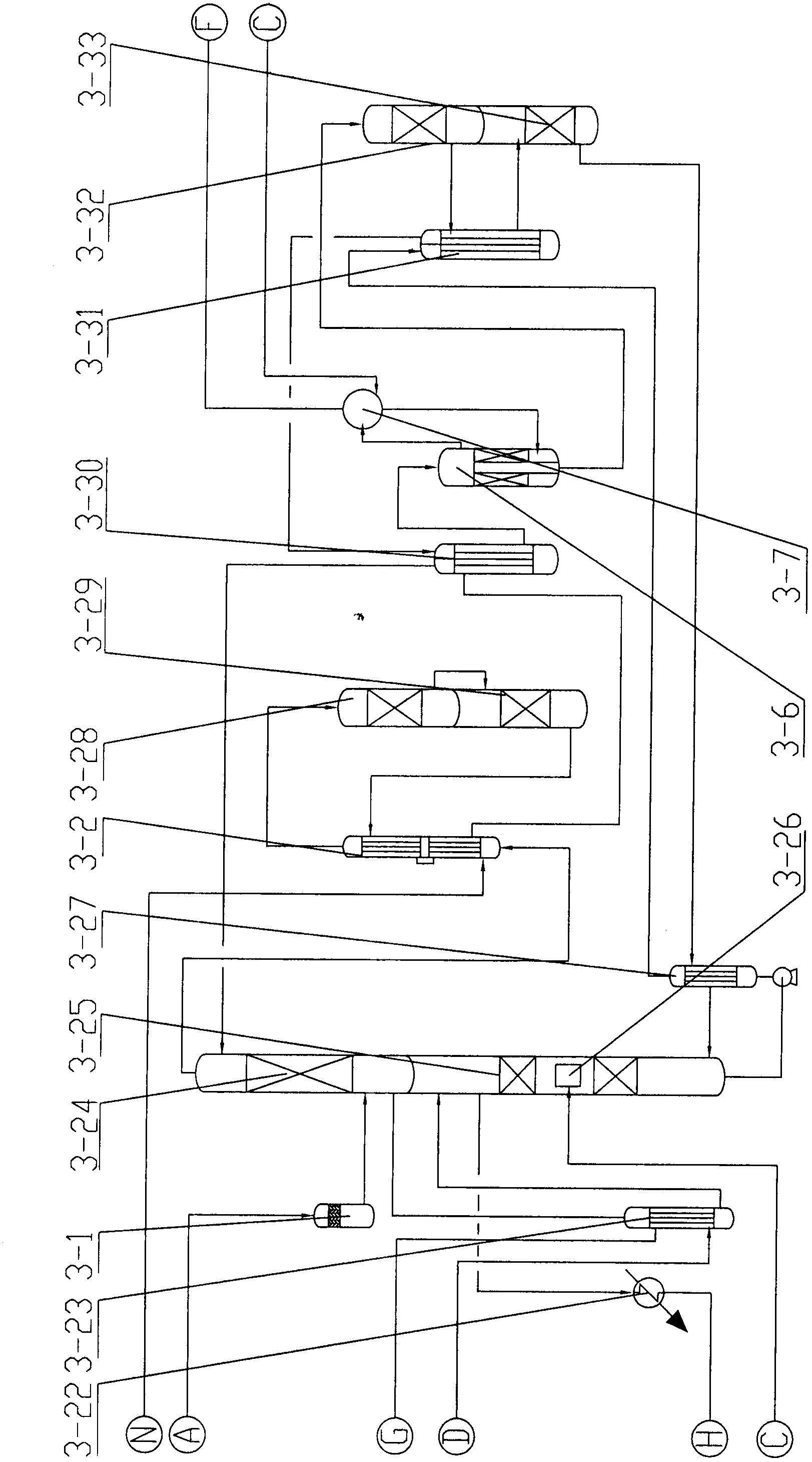
[0077] as attached image 3 As shown: the raw gas from the gasification device enters the interior of 1# gas-liquid separator 3-1 for downward swirling (the gas swirls downward to facilitate separation), and after the dust and water are separated, they reverse 180° and enter the center pipe, and then It is further filtered through a stainless steel wire mesh to ensure that the gas is clean.

[0078]The raw material gas after separation of oil and water enters the saturation tower 3-24 to exchange heat with the hot water entering the tower for humidification, and the gas exiting the saturation tower 3-24 is heated to 300-350°C by the raw gas heater 3-2 and enters the first stage of the intermediate transformation furnace Layer 3-28 reacts, and then enters the second stage of medium transformation bed layer 3-29 for reaction. After the reaction, the transformed gas enters the raw material gas heater 3-2 at 420-440°C, and enters the first-stage cooler 3 after the temperature drop...


PUM


Abstract

The invention relates to a water heat-transfer shift process for by-product high-grade steam energy-saving deep conversion. According to the process, a primary water heat-transfer shift converter and a secondary shift converter are adopted, CO in feed gas reacts with H2O to generate H2 and CO2 under the catalysis of a Co-Mo (copper-zinc) catalyst, and CO in shift gas coming out of a shift system is less than or equal to 0.1% (dry basis). In the process, CO is subject to deep conversion, the feed gas (containing water gas, semi-water gas, natural gas conversion gas or coke-oven gas conversion gas) utilization rate is high, the shift catalyst is not overheated, and the catalyst has a long service life; meanwhile, by-product saturated steam with the pressure of 0.5 to 9.0 MPa is generated, sensible heat and latent heat in the shift gas are further recovered by deoxygenated water and desalted water, low-grade heat energy is converted into high-grade heat energy, cooling water consumption is reduced, the temperature of` the shift gas coming out of a process system is lower than or equal to 40 DEG C, equipment is few, the flow is short, the investment is small, and the resistance is low (less than or equal to 0.05MPa).

Description

technical field [0001] The invention belongs to the field of raw material gas CO transformation in coal chemical industry, natural gas chemical industry, coal bed gas chemical industry and biogas chemical industry, and especially relates to pressurized pulverized coal continuous gas such as aerospace, coal water slurry Texaco, GSP, multi-nozzle, Shell (shell) and so on. The field of high water-gas ratio and high CO transformation produced by the furnace, the field of low water-gas ratio and high CO transformation produced by fixed-bed batch gasification, and the field of low water-gas ratio and high CO transformation produced by atmospheric pulverized coal continuous gasifier. In particular, a by-product high-grade steam energy-saving deep conversion water transfer heat conversion process. Background technique [0002] Currently, making CO and H 2 O generates CO 2 and H 2 achieve the conversion of CO into H 2 The purpose, the basic principle is: in the presence of cataly...

Claims


Application Information

Patent Timeline
IPC IPC(8): C01B3/16
CPCY02P20/10Y02P20/52Y02P20/584
Inventor 王庆新
Owner NANJING DUNXIAN CHEM TECH
Why Eureka
Try Eureka