
A kind of active optical module controller

A module controller, source light technology, applied in the direction of optical fiber transmission, etc., can solve the problems of miniaturization of optical modules, difficult production process, high production cost, reduce the risk of mutual interference of small signals, reduce space and chip tube The number of feet, the effect of improving overall stability

Active Publication Date: 2015-12-09
DONGGUAN MENTECH OPTICAL & MAGNETIC CO LTD
View PDF3 Cites 0 Cited by
  • Summary
  • Abstract
  • Description
  • Claims
  • Application Information

AI Technical Summary

Problems solved by technology

Image 6 As shown, this type of chip has functional modules such as analog-to-digital converters, digital potentiometers, and logic circuits inside. It involves CMOS integration technology and digital circuit lithography technology, and the production process is difficult; this type of chip has many pins and a large package. , which is not conducive to the miniaturization of optical modules; and the high production cost is not conducive to the promotion and use of optical modules.

Method used


Image

  • A kind of active optical module controller
  • A kind of active optical module controller
  • A kind of active optical module controller

Examples


Embodiment 1

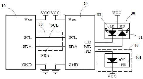
[0026] like figure 1 As shown, the photodiode unit 40 includes a PIN diode 401 , one end of the PIN diode 401 is electrically connected to the PD end of the laser driver chip 20 , and the other end of the PIN diode 401 is electrically connected to the DC power supply VCC.

Embodiment 2

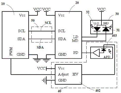
[0028] like figure 2 As shown, the photodiode unit 40 includes a DC / DC unit 402 and an avalanche photodiode 403, the control unit 10 is provided with a pulse width modulation terminal, and the input terminal of the DC / DC unit 402 is electrically connected to the pulse width modulation terminal. The output end of the DC / DC unit 402 is electrically connected to one end of the avalanche photodiode 403, and the other end of the avalanche photodiode 403 is electrically connected to the PD end of the laser driver chip 20; the control unit 10 Outputting different pulse width modulation (PWM) signals according to needs to change the output voltage of the DC / DC unit 402 so that the avalanche photodiode 403 works at an optimal working point.

Embodiment 3

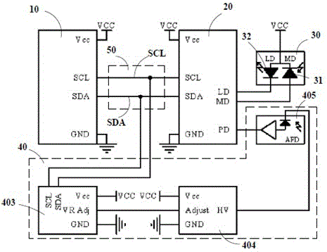
[0030] like image 3 As shown, the photodiode unit 40 includes a digital potentiometer 403, a DC / DC unit 404 and an avalanche photodiode 405, and the input terminals of the digital potentiometer 403 are electrically connected to the bidirectional data line SDA and the clock line SCL respectively, The output end of the digital potentiometer 403 is electrically connected to the input end of the DC / DC unit 404, the output end of the DC / DC unit 404 is electrically connected to one end of the avalanche photodiode 405, and the avalanche photodiode 405 is another One end is electrically connected to the PD end of the laser driver chip 20; the control unit 10 controls the digital potentiometer 403 through the serial data bus 50 to change the resistance value of the digital potentiometer 403, and the digital potentiometer 403 is connected to the DC The / DC unit 404 is connected in series, and the output voltage of the DC / DC unit 404 is changed by changing the resistance of the digital ...


PUM


Abstract

The invention discloses an active light module controller, which comprises a control unit, a laser driving chip, a laser diode unit and a photodiode unit, wherein the control unit is used for controlling the laser driving chip via a series data bus; the series data bus consists of a bidirectional data line and a clock line; the grounding ends of the control unit and the laser driving chip are respectively grounded; one end of the laser diode unit is electrically connected to the LD end of the laser driving chip, and the other end of the laser diode unit is electrically connected with the MD end of the laser driving chip; and one end of the photodiode unit is electrically connected to the PD end of the laser driving chip, and the other end of the photodiode unit is electrically connected to a DC power supply. According to the invention, the bidirectional data line and the clock line are electrically connected between the control unit and the laser driving chip, so that the occupied space is small, a circuit space and the quantity of chip tube pins are reduced, interference between the interconnection cost and the signal is reduced, and the integral stability is improved.

Description

technical field [0001] The invention relates to the technical field of optical fiber communication, in particular to an active optical module controller. Background technique [0002] With the development of communication technology, intelligent optical fiber communication network continues to popularize, a large number of applications of optical fiber transmission equipment, and the core device of optical fiber communication equipment, the active optical module is getting faster and faster, the package is getting smaller and smaller, and the degree of intelligence is getting more and more intelligent. high. The intelligent optical module controller requires monitoring of the optical module's operating temperature, operating voltage, bias (Bias) current, transmitted optical power, received optical power, error monitoring (Tx_Fault), and loss of signal (LOS) during normal operation. Perform real-time monitoring. [0003] In order to realize the monitoring and diagnosis of t...

Claims


Application Information

Patent Timeline
Patent Type & Authority Patents(China)
IPC IPC(8): H04B10/25
Inventor 谢光明李玲彭彦辉
Owner DONGGUAN MENTECH OPTICAL & MAGNETIC CO LTD
Learn More