Focusing rotary scanning photoacoustic ultrasonic blood vessel endoscope imaging device and focusing rotary scanning photoacoustic ultrasonic blood vessel endoscope imaging method

A rotary scanning and focusing technology, applied in catheters, surgery, etc., can solve the problems of poor receiving efficiency of acoustic elements, poor photoacoustic image resolution, high laser energy, etc., to reduce detection difficulty, simple structure, good resolution

Active Publication Date: 2012-10-24
SOUTH CHINA NORMAL UNIVERSITY
View PDF3 Cites 53 Cited by
  • Summary
  • Abstract
  • Description
  • Claims
  • Application Information

AI Technical Summary

Problems solved by technology

[0005] The disadvantage is that the pulsed laser beam of this technology expands in the conical mirror and excites the whole inside of the blood vessel at the same time, and the laser energy required is large; and because the pulsed laser is not converged, the resolution of the photoacoustic image is not good. In addition, the device The probe uses 64 sound-sensitive elements, and the receiving efficiency of a single sound-sensitive element is poor and the structure is complicated

Method used


Image

  • Focusing rotary scanning photoacoustic ultrasonic blood vessel endoscope imaging device and focusing rotary scanning photoacoustic ultrasonic blood vessel endoscope imaging method
  • Focusing rotary scanning photoacoustic ultrasonic blood vessel endoscope imaging device and focusing rotary scanning photoacoustic ultrasonic blood vessel endoscope imaging method
  • Focusing rotary scanning photoacoustic ultrasonic blood vessel endoscope imaging device and focusing rotary scanning photoacoustic ultrasonic blood vessel endoscope imaging method

Examples


Embodiment 1

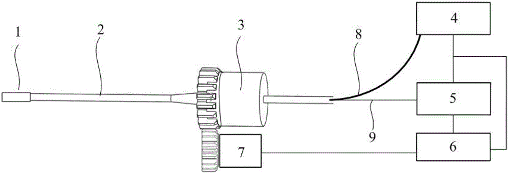
[0047] The schematic diagram of the structure of the focused rotary scanning photoacoustic ultrasound endoscopic imaging device is as follows: figure 1 As shown: among them, 1 is a photoacoustic ultrasound endoscopic imaging probe, 2 is a medical sleeve, 3 is a rotating connection part, 4 is a pulse laser, 5 is an ultrasonic pulse transmitter receiver, 6 is a data acquisition computer, 7 is a step Into the motor, 8 is the pulse laser conduction optical fiber, and 9 is the signal wire.

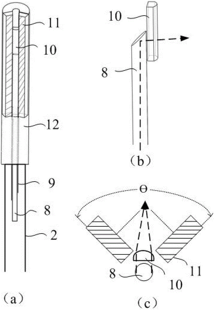
[0048] figure 2 (a) is the overall structural diagram of the photoacoustic ultrasound endoscopic imaging probe, in which, 2 is a medical sleeve, 8 is a pulsed laser transmission fiber, 9 is a signal wire, 10 is a cylindrical focusing lens, and 11 is an acoustic sensor , 12 is the basic fixture; (b) is the schematic diagram of the laser transmission part of the photoacoustic ultrasound endoscopic imaging probe, in which 8 is the pulsed laser transmission fiber, and 10 is the cylindrical focusi...


PUM


Abstract

The invention belongs to the technical field of non-destructive testing and measuring, and discloses a focusing rotary scanning photoacoustic ultrasonic blood vessel endoscope imaging device and a focusing rotary scanning photoacoustic ultrasonic blood vessel endoscope imaging method. The device comprises a photoacoustic ultrasonic endoscope imaging probe, a rotating connecting part and a peripheral circuit part, wherein pulse laser generates 90-degree reflection at the light outlet end and is irradiated on the blood vessel wall after being gathered by a cylindrical surface light gathering lens, photoacoustic signals are generated, a sound-sensitive element receives the photoacoustic signals, the photoacoustic signals are collected and recorded after being converted, the synchronous working of a data collector and a pulse laser is realized, triggering signals generated by the pulse laser trigger an ultrasonic pulse emitting and receiving device to emit electric signals, the electric signals trigger the sound-sensitive element to emit ultrasonic signals, the ultrasonic signals are reflected after reaching the blood vessels, are received by sound-sensitive elements and are collected and recorded after being converted, a step motor drives the device for carrying out scanning to obtain the whole blood vessel fault data, and photoacoustic and ultrasonic images are obtained after the processing. The sound-sensitive elements are shared by ultrasonic and photoacoustic images, and the high-resolution and high-sensitivity blood vessel internal ultrasonic photoacoustic imaging can be realized.

Description

technical field [0001] The invention belongs to the technical field of non-destructive testing and measurement, and in particular relates to a focusing rotary scanning photoacoustic ultrasonic endoscopic imaging device and an imaging method thereof. Background technique [0002] Modern medicine has put forward higher and higher requirements for the accuracy of blood vessel detection. Although traditional methods, including magnetic resonance angiography and angiography, can better present the external shape or internal contour of blood vessels, they cannot provide Local detail information of vessel wall and lumen. Intravascular imaging technology is the product of the continuous development and integration of endoscopic technology and computer, microelectronics, digital image processing and other technologies. It can image the section of the blood vessel from the inside of the blood vessel with a unique perspective. It can observe the fine structure of blood vessel wall an...

Claims


Application Information

Patent Timeline
Patent Type & Authority Applications(China)
IPC IPC(8): A61B8/12
Inventor 杨思华张建纪轩荣邢达
Owner SOUTH CHINA NORMAL UNIVERSITY
Why Eureka
Try Eureka