
System for rotational flow dust removal and recovery of blast furnace roof raw gas and recovering method of blast furnace roof raw gas

A recovery system and furnace top gas technology, applied in the direction of dust collector, etc., can solve the problems of bag filter wear, easy dust deposition, affecting economic benefits, etc., to achieve the effect of improving service life, good dust removal effect and reducing cost

Inactive Publication Date: 2012-10-31
唐忠库
View PDF10 Cites 17 Cited by
  • Summary
  • Abstract
  • Description
  • Claims
  • Application Information

AI Technical Summary

Problems solved by technology

However, due to the large particles in the flue gas released from the blast furnace, the bag filter is severely worn, which directly affects economic benefits; in addition, most of the bag filter is cleaned by gas back blowing, and the filter material is back blown once every pulse , the dust collected on the surface of the filter material falls under the action of back-blowing air. Generally, high-pressure nitrogen gas back-flushing or oscillating mechanism is used for bag dust removal. Among them, nitrogen gas is widely used in steel mills, which is relatively scarce and expensive. In addition, if the nitrogen content in the gas pipe network is too high, it will also affect the secondary utilization and combustion quality of the gas; secondly, the raw gas released from the equal pressure of the weighing tank enters the cyclone dust collector for preliminary dust removal through the equal pressure release pipe. After that, a release occurs, and the release process in the "material tank" is a process in which the pressure changes from about 0.2mpa to 0.015mpa and the speed changes from high speed to low speed.
Due to changes in pressure and wind speed, the consequences are large impact on the bag, large wear, and large pressure changes in the pipeline, which cannot form the overall flow velocity in the pipeline, dust is easy to deposit, and the recovery time is too long

Method used


Image

  • System for rotational flow dust removal and recovery of blast furnace roof raw gas and recovering method of blast furnace roof raw gas
  • System for rotational flow dust removal and recovery of blast furnace roof raw gas and recovering method of blast furnace roof raw gas
  • System for rotational flow dust removal and recovery of blast furnace roof raw gas and recovering method of blast furnace roof raw gas

Examples


Embodiment Construction

[0025] The specific implementation manner of the present invention will be described below in conjunction with the accompanying drawings.

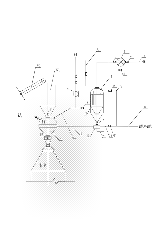
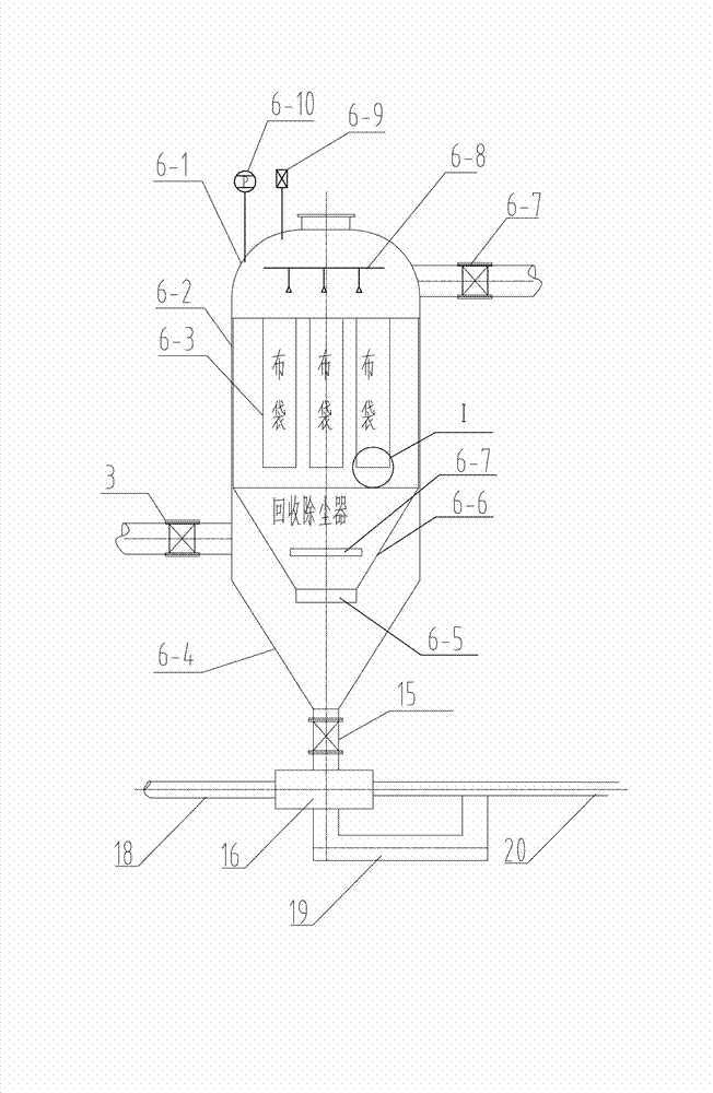
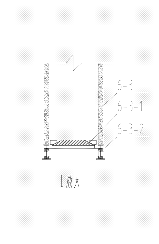
[0026] Such as figure 1 , figure 2 , image 3As shown, the blast furnace top waste gas cyclone dust removal recovery system of the present invention includes a blast furnace top waste gas output pipeline 2 connected to a blast furnace top tank 1, a blast furnace top waste gas shut-off valve 3, a blast furnace gas bag filter 6, The clean gas pipe network 10 and the clean gas cut-off valve connected with the blast furnace gas bag filter 6, the blast furnace gas bag filter 6 consists of an upper semicircular limelight shell 6-1, a middle cylindrical shell 6- 2 and the outer casing composed of the lower conical casing 6-4, the clean gas outlet connected to the clean gas pipe network 10, the pressure sensor 6-10 and the oxygen meter arranged on the upper semicircular air head casing 6-1 6-9, the dust removal bag group 6-3 arranged in the ga...


PUM


Abstract

The invention relates to a system for rotational flow dust removal and recovery of blast furnace roof raw gas and a recovering method of the blast furnace roof raw gas. According to the system and the method, the blast furnace roof raw gas which is diffused in a pressure equalizing mode from a blast furnace charging bucket is directly fed into a blast furnace gas bag-type dust remover for dust removal, a built-in type round platform-shaped cyclone is additionally arranged on the lower portion of a casing of the blast furnace gas bag-type dust remover, the raw gas which enters the blast furnace gas bag-type dust remover rotates in a tangential direction inside an annular cyclone chamber, then enters an upper portion gas purification chamber and uniformly passes through dust collecting bag groups which are arranged at intervals under the action of a guide plate for dust removal, the structure is good in dust removal effect, and the temperature of the raw gas which enters upper portion gas purification chamber is greatly reduced, so that the service life of bags is effectively prolonged.

Description

technical field [0001] The invention belongs to the gas purification process in blast furnace smelting production in the metallurgical industry, and in particular relates to a blast furnace top waste coal gas cyclone dust removal recovery system and a recovery method thereof. Background technique [0002] According to statistics, there are more than 400 large, medium and small blast furnaces in the country. The basic principle of the gas recovery system of the furnace top feeding system is: the blast furnace material is transported to the "storage bin" by the belt conveyor (generally quantitative loading), after the furnace charge is supplied, the feeder valve F2 is opened, and the charge enters the "storage tank". "; After the "silo" has unloaded the material, close the valve F2 of the material bin. At this time, the "material bin" can continue to load the material, and then open the semi-clean gas pressure equalizing valve F10 to equalize the pressure of the material t...

Claims


Application Information

Patent Timeline
IPC IPC(8): C21B7/22
Inventor 唐忠库
Owner 唐忠库
Learn More