Visualized microscopic model of real core and manufacturing method of visualized microscopic model of real core

A technology of real cores and microscopic models, applied in teaching models, educational appliances, instruments, etc., can solve the problems of easily damaged core pores physical and chemical properties, epoxy resin sealing core pores and other problems

Active Publication Date: 2012-11-07
TECHNICAL INST OF PHYSICS & CHEMISTRY - CHINESE ACAD OF SCI
View PDF12 Cites 36 Cited by
  • Summary
  • Abstract
  • Description
  • Claims
  • Application Information

AI Technical Summary

Problems solved by technology

[0005] In the above two models, during the bonding process of the core bottom sheet, plexiglass monomer or rosin was injected into the core in order to protect the pores of the sandstone. Because the plexiglass monomer or rosin is eas

Method used


Image

  • Visualized microscopic model of real core and manufacturing method of visualized microscopic model of real core
  • Visualized microscopic model of real core and manufacturing method of visualized microscopic model of real core
  • Visualized microscopic model of real core and manufacturing method of visualized microscopic model of real core

Examples


Embodiment 1

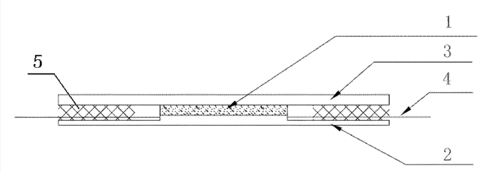
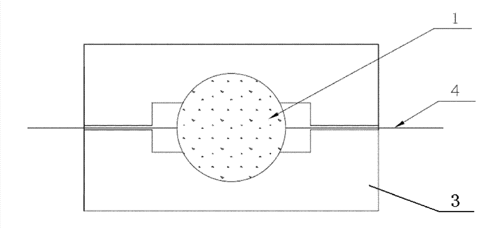
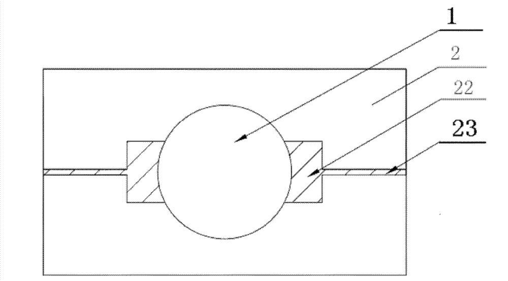
[0035] Figure 1(a)(b) and figure 2 As shown, the present embodiment provides a real rock core visual microscopic model, which is a high-temperature pressure-formed model including a real rock core slice 1, a plexiglass slide 2, a plexiglass cover 3 and a needle 4, wherein the real rock core The sheet 1 is sandwiched between the plexiglass cover sheet 3 and the plexiglass slide 2, and the plexiglass slide 2 is provided with connected guide grooves 22 and needle grooves 23 on both sides of the real rock core slice 1, and the guide groove 22 It is connected with the real rock core piece 1; the pinhole at one end of the needle head 4 is in the guiding groove 22, and is in contact with the side wall of the guiding groove 22 at the end of the real rock core piece.

[0036] When preparing the real rock core visual microscopic model, the following steps are adopted:

[0037] (1) Processing of real rock core slices: After the real rock core slices 1 are washed with oil and dried, one fa...

Embodiment 2

[0044] The difference between this embodiment and embodiment 1 is:

[0045] When preparing the real rock core visual microscopic model, the following steps are adopted:

[0046] (1) Processing of real rock core slices: after the real rock core slices 1 are washed with oil and dried, one face of the real rock core slices 1 is ground on the grinding machine, and a section of 4 mm long is cut, and the ground surface is ground Bond it to a clean ground glass piece with optical resin glue, and then grind the core piece to about 0.2 mm in a grinder.

[0047] (2) Pretreatment of the rock core sheet: soak the processed real rock core sheet 1 in acetone solvent overnight, the optical resin glue on the real rock core sheet 1 and the ground glass sheet has been completely dissolved, and dry the real rock core sheet 1;

[0048] (3) Processing of plexiglass slides and plexiglass cover slips: two plexiglass sheets with a length of 65 mm and a width of 37 mm are cut out from a 2 mm thick pl...

Embodiment 3

[0052] The difference between this embodiment and embodiment 1 is:

[0053] When preparing the real rock core visual microscopic model, the following steps are adopted:

[0054] (1) Processing of real rock core slices: After the real rock core slices 1 are washed with oil and dried, one face of the real rock core slices 1 is ground on the grinding machine, and a section of 3 mm long is cut, and the ground surface is ground Bond it to a clean ground glass piece with optical resin glue, and then grind the real core piece 1 to about 0.2 mm in a grinder;

[0055] (2) Pretreatment of rock core slices: soak the processed real rock core slices 1 in a mixed solvent of ethanol and acetone for more than 2 days until it is observed that there is no viscous soluble glue on the real rock core slices 1 and ground glass slices, that is, optical resin glue Completely dissolved, dry the real core piece 1;

[0056] (3) Processing of plexiglass slides and plexiglass cover slips: two plexiglass...


PUM


Abstract

The invention relates to a visualized microscopic model of a real core and a manufacturing method of the visualized microscopic model of the real core. The model comprises a real core sheet, an organic glass cover plate, an organic glass slide and a needle and is formed via the pressure at high temperatures; the real core sheet is milled to be visualized and is then clamped between two pieces of the organic glass; the needle is firstly fixed well, and the organic glass cover plate is then arranged; at a high temperature and at a high pressure, the organic glass is softened to be adhered more tightly with the core sheet; and the model is formed by cooling. According to the visualized microscopic model and the manufacturing method provided by the invention, the physico-chemical properties of the real core are kept, and the distribution and flowing condition of the multi-phase fluid in the porous medium pores are observed, so that the visualized microscopic model and the manufacturing method play an important role in studying the percolation mechanism and enhancing the yield of the polymer microspheres.

Description

technical field [0001] The invention relates to a microcosmic model and a manufacturing method thereof for research on enhanced oil recovery, seepage mechanism research and tertiary oil recovery effect evaluation, in particular to a microcosmic model of real rock core visualization and a manufacturing method thereof. Background technique [0002] At present, most oil fields in our country have entered the high water cut period of secondary oil recovery. It is of great practical significance to study how to further increase the oil recovery rate and realize the full utilization of resources. At present, there are mainly three kinds of physical models in the study of enhanced oil recovery technology and seepage mechanism: (1) The physical model of cylindrical natural core and artificial cylindrical quartz sand core is the one commonly used in physical simulation of flooding at present. Although the model well maintains the pore structure and mineral composition of the real for...

Claims


Application Information

Patent Timeline
IPC IPC(8): G09B23/40
Inventor 吴飞鹏蔡永富施盟泉
Owner TECHNICAL INST OF PHYSICS & CHEMISTRY - CHINESE ACAD OF SCI
Why Eureka
Try Eureka