Ecological power unit

A power unit and ecological technology, applied in the field of ecological propulsion devices, can solve problems such as radiation waste gas, impact on sustainable development, and accompanying

Active Publication Date: 2014-12-10
吉尔伯特·里
View PDF5 Cites 0 Cited by
  • Summary
  • Abstract
  • Description
  • Claims
  • Application Information

AI Technical Summary

Problems solved by technology

[0004] Unfortunately, all these modes of energy generation are inevitably accompanied by the notorious greenhouse gases, radiation waste, CO 2 generation, which seriously affects sustainable development

Method used


Image

  • Ecological power unit
  • Ecological power unit
  • Ecological power unit

Examples


Embodiment Construction

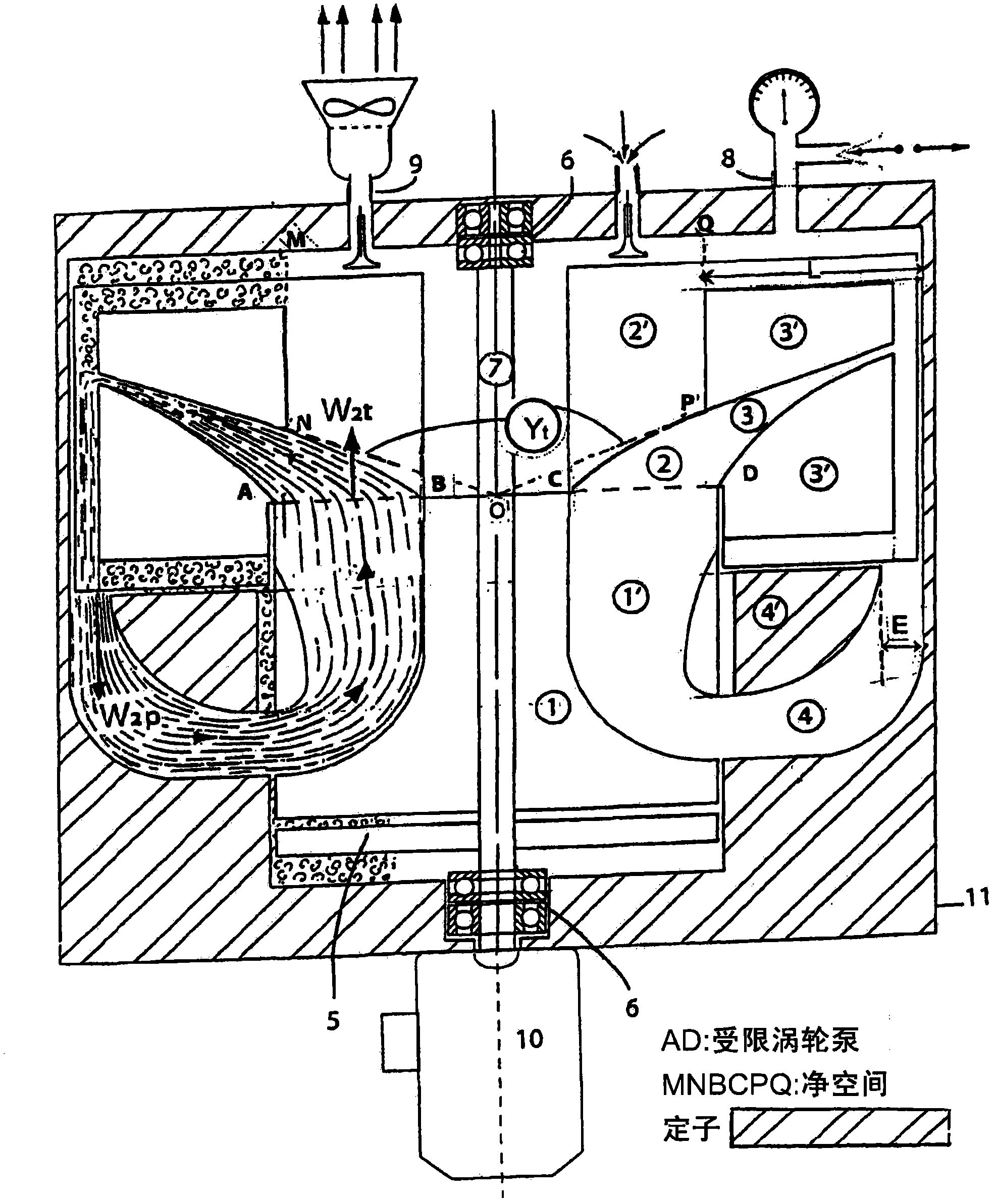
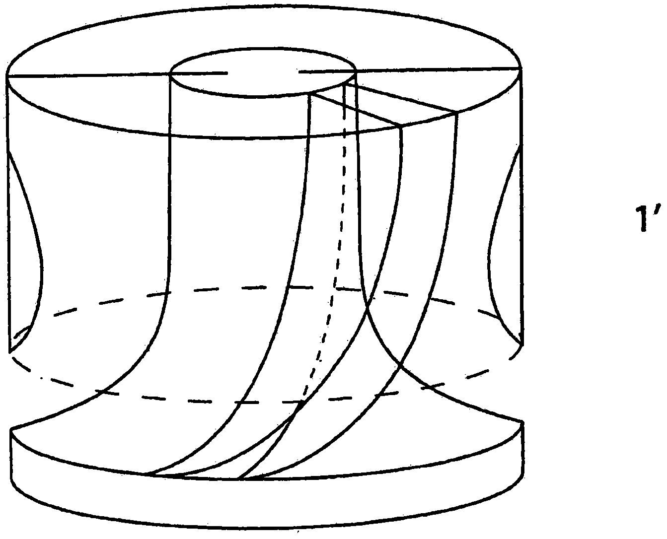
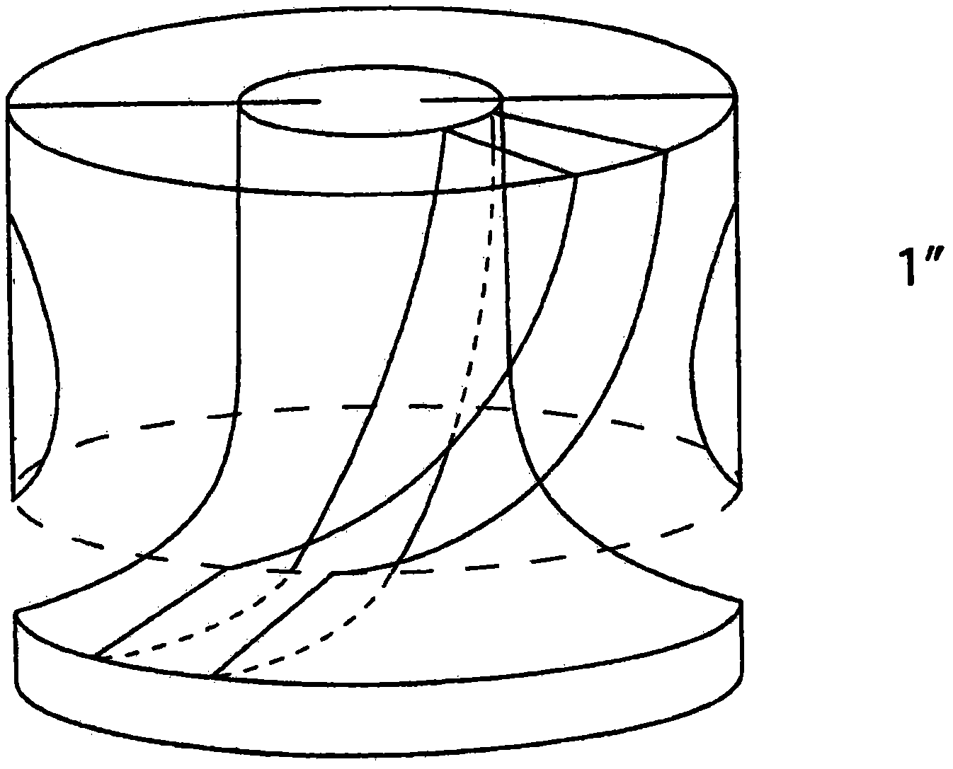
[0039] Referring to these figures, the device consists of a special type of Francis turbine (1) whose impeller blades (1') adjust the velocity vector at the inlet, C 1t ( Figure 5 ) is perpendicular to the rotation axis at 90°, and extends radially to the outlet at the minimum relative speed in the axial direction, which is equal to the circumferential speed r×ω (r is the radius of the turbine, and ω is the angular velocity). At the outlet, the fluid is collected in the free area MADQ (MNBCPQ is the net free area) defined by the linear radial pump (2) whose fins (2') are formed with the turbine blades (1') in order to maintain flow continuity joint.

[0040] The fins (2') are held and reinforced by two spatially streamlined crown structures (3'), forming a unit (3) for directing fluid flow. For better fluid transport, these units (3) conform to the boundary of the fixed streamline Yi ( Figure 4 ), regardless of the rotational speed. The relative velocity at the pump outl...


PUM


Abstract

The invention relates to an ecological thrusting device enabling optimum thrust independent from the outside environment. It consists of a special Francis turbine (1) from which the fluid is axially ejected at the outlet of the vane (1'), at a relative speed W2t, and is collected in a defined free space of a straight radial pump (2). Under the action of the centrifugal force, the limit of the current lines forms a fixed virtual barrier Yt, thus preventing the centrifuged fluid from reaching the bottom of the pump in the free space area MNBCPQ, thereby eliminating the antagonistic force exerted on said zone. As a result, the thrusting force exerted on the turbine by the fluid remains intact. As the fluid leaves the pump, it is axially reinjected at a relative speed W2p into a tank (4) for resupplying the turbine. There is therefore an energy exchange between the pumps and the turbine that form a closed circuit, the entire system being driven by a motor (10). It is shown that the thrust force P=(½) ppiomega2 r4; p being the density of the centrifuged fluid in en Kg / m3; omega being the angular speed of the turbine in rad / s; and r its radius in metres and P in Newtons. The calculation shows that the amount of thrust generated is very high; said thruster can be used to generate mechanical energy anywhere in space, and especially to drive the most highly efficient flying machines.

Description

technical field [0001] The invention relates to an ecological propulsion device that achieves optimal thrust with high precision and is independent of the external environment. Background technique [0002] In the 18th century, humans produced mechanical energy by separating water molecules (evaporation by heating). This is the origin of the steam engine or external combustion engine. The internal combustion engine, or spark ignition, appeared in the late 19th century. At this time, instead of separating the water molecules, they are completely fragmented (combustible) by oxidation (combustion) to generate mechanical energy. It should be noted that in a steam engine, fuel molecules (coal) are also broken up during combustion in order to heat and vaporize (separate) water molecules. [0003] A technological breakthrough occurred in the middle of the 20th century, which completely changed the destiny of mankind: instead of destroying water molecules, atoms were destroyed, o...

Claims


Application Information

Patent Timeline
Patent Type & Authority Patents(China)
IPC IPC(8): F01D1/10F01D1/12F01D1/14F03B3/10F03B17/00F03G7/10
CPCF03G7/10F01D1/08F01D1/14Y02E10/223F03B17/005Y02E10/20F03H99/00F01D1/12F03B3/106F01D1/10Y02T50/60
Inventor 吉尔伯特·里
Owner 吉尔伯特·里
Why Eureka
Try Eureka